OFFICIAL: Auto to Manual (5 Speed) Transmission Swap
Posted: Mon Mar 20, 2023 10:01 am
THIS THREAD IS CURRENTLY A WORK IN PROGRESS....
Disclaimer: All information on this website is to be used as a REFERENCE ONLY. Canadian Prelude Club and I take no responsibility what so ever for problems that may occur for those who use and apply this information. Also, this information is specific to the 5th Generation Honda Prelude (1997 to 2001) and may not apply to all the model years. Informational purposes only, means just that.
List of Parts:
* MOST LIKELY THESE WILL BE ATTACHED TO TRANNY (DOUBLE CHECK)
**This list of parts consists of the main components needed and does not include every little nut, bolt, and bracket. You get the idea.
Where to start?
Make sure you have a lot of metric wrenches, sockets (short and deep), various ratchets (1/4, 1/2, 3/8), and a good torque wrench, If you don't have access to a vehicle lift, I would suggest you find one or be prepared for a struggle. I will also include the necessary wiring diagrams we created to get the car running. It is a good idea to find all the pages of the Helms that you will be using and place post-its at the top.
Auto Transmission Removal Tips
The Helms is good tool and give a protocol to the dismantling process. Start on page 14-125 and continue to do so until you reach page 14-127. Here you have two options. The first is to follow the book, but if you are having trouble separating the lower arm like I did, you can unfasten the sway bar, radius rods, and take the damper fork bolts out. This will allow you enough swing to remove the axles. If you don't have a good ball joint remover, I recommend using our method. . We tried two of the Pitman Pullers with no luck. I actual ripped a seal trying. If you can't get the Honda tool listed in the Helms, just use the method we figured out. Now you are back to following the Helms, but the Helms only take you so far. The book doesn't expect you to swap trannies. With the tranny out you can now get the shift cable out and put the new 5spd one in. This looks tricky at first because it looks like you may have to drop your exhaust to get access, but it will unbolt with a little creativity. (my header and cat bolts are so rusted we would of had to cut them off) The space it tight, but one you undo the heatshield protecting the cable, you can unbolt the plate holding the cable in place and be glad you didn't have to take the exhaust off to gain access. You can use page 14-204 for a reference. At this point you might as well put the replacement 5spd cables in place. The great thing about this swap is 99% bolts right up and a lot of the nuts and bolt can be reused..
Manual Transmission Installation Tips
Page 12-3 is a good reference page to stick a bookmark in. Start with pages 12-8 to 12-11 to get you started. This will cover the flywheel and clutch installation. When tightening up the flywheel and clutch, the Helms shows this being done using a ring gear holder (Honda tool). We did not have this tool so we just held the crank in place from the other side (located in driver side wheel well) with a breaker style wrench. Now you will skip to page 13-10 to start the installation of the trans. You will continue from that page until the book tells you to reverse the order of the removal instructions. At this point read up on the instructions and get used to reading the steps in reverse and figuring out how to apply them properly. Continue to read/install the tranny and you will notice on page 13-7 that they removed the lower header pipe. You DO NOT need to remove this pipe. I'm not sure why this is in the book because we had no trouble with it being in place. I honestly don't think we would have been able to remove it without cutting the bolts anyway. Don't forget to run the hydraulic lines. The line as you can see will be very hard to fish through all the stuff in your engine compartment. We go a little creative and ran it where ever it fit the best. We used a line bender to help us reroute it. It basically your call on how you should run the lines, but make sure you don't kink the line too much. I used zip-ties to fasten the hydraulic line to various point.
Clutch Master Cylinder Installation / Fabrication Tips
This can get tricky because this is where you start hacking up your car. Page 12-5 will give some pointers. Either find someone with a Prelude to use as a guide or just guestimate. The easiest way to mount the master cylinder is to make a template out of cardboard so you can easily make your marks before you drill. What you can do is take your clutch pedal and hold it up to about where you "think" you want it and and make some marks. I also recommend making two plates from 18 Gauge steel to help stiffen the weak firewall. This will help make the clutch pedal sturdy because when doing a swap, you will most likely not have a bracket to help hold the clutch pedal up. These plates are real easy to make. Just cut them a little bigger than your master cylinder template (that you made earlier), but not so big that they will not mount flush against the firewall (you will get my point when you start doing it). Just put one plate on the outside (against firewall) and the other inside the passenger compartment against the firewall. Now you can mount the clutch pedal. It will bolt right on the the backside of the master cylinder.
Clutch Pedal and Brake Pedal Installation Tips
This section is very Important
Remove the old brake pedal assembly and put the 5spd specific one in its place. Hook up the brake switch and make sure it works properly. Used page 19-5 for pointers. I've heard that some people cut their brake pedal, but I DO NOT recommend it. Installation of the clutch pedal may be easier if you have the brake pedal off at that time. Its up to you and how well you work in tight spaces.
Time to mount the clutch pedal. Its is best to have a helper present to hold the master cylinder while you tighten down the nuts. Before you start tightening, you need to check to see if your clutch pedal assembly came with spacers SEE PIC BELOW. Most likely they will not, but you may get lucky. These spacers are located behind the pedal assembly against the firewall. My pedal did not come with these spacers and we did not know that they even existed at first. My clutch was slipping more and more as the car warmed up, but would stop slipping if cooled down by driving on the highway. This was real confusing and time consuming considering we had not idea what the problem was. After a quick inspection of my friends Prelude, I noticed the spacers. Problem solved. I obviously did not have the spacers, so I looked around for something the same size. Luckily the self locking nuts that I removed from the damper forks (page 13-8 show a good pic) worked. You are supposed to replace these anyway, so we got lucky. What we did was position the master cylinder with the two fabricated plates in place, put the two nuts on (with the flat side against the plate), and a washer to the side closest to the passenger compartment. Now just tighten everything up and make your adjustments using page 12-4 and 12-5 as a reference. There may be some trouble shooting involved to make your clutch operate properly. Depending on your application and fabrication pieces, you may need to add/remove washers to the backside of your clutch pedal assembly to get the proper pedal rod movement. The best way to test your spacer set-up is to do some city style driving (stop and go) and stay away form the highway because it will cool off your clutch and cause it not to slip. Luckily we got it right on the first try, buy you may need to add/remove accordingly. Remember that every time you make changes to your pedal, you will need to make the proper adjustments found on page 12-4.
Bleeding the Clutch System
Now that you have everything together the clutch lines will be bone dry. We tried to bleed the conventional way for quite some time without luck. You need a vacuum bleeder to pull the fluid through the system. You will thank yourself.
Shift Assembly and Gauge Cluster Removal / Installation
Use page 20-45 to aid in the removal of your center console. You can now remove all the automatic shifter assembly and related items. Now just bolt up your new gear shift mechanism using page 13-13 as a reference. Replacing the gauge cluster is just as easy, as well as optional. The auto cluster will work just fine. The 5spd cluster is plug-in-play (minus the plug for the gear selection). First, remove the two screws holding the trim piece in place, then pry the panel working gently because you don't want to mark it up. Now you have access to to the actual cluster. Use page 23-65 for reference.
Wiring and Computer Related Issues
You can use your auto ECU if you like (NOT RECOMMENDED) and do some creative wiring to get rid of the check engine light. There will be some idling issues (randomly pulsing idle) but the check engine light will not be on. Page 11-4 will give you an idea of where the components are. Follow the instructions closely starting on page 23-195. I did run the auto ECU for a while, but have since gone to a Honda dealer to have the 5spd ECU programmed with my immobilizer code and it works great!
Wiring for Prelude Auto Trans to 5 Speed Tranny Swap
Clutch/ Starter Switch
First and most important mod is to stop your lude from being started while the clutch is engaged, cause you might launch it through your garage wall. Luckily Honda has provide a very easy way to kill the starter. Your "immobilizer" sends a signal to this starter relay, to allow power to pass to the starter. We will be using the clutch switch to provide this signal instead.
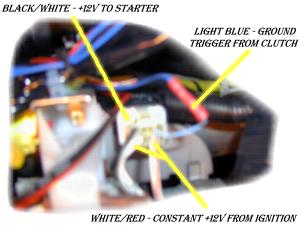
1. Locate the starter relay under the dash. My pic is fussy cause the camera doesn't focus good up close. You should find it on the back side of the dash panel below the steering column, the relay is positioned just about in-line with the clutch pedal, and the plug is facing down. It is easily identifiable by the large gauge wires it uses. It has two 10ga white/red stripe, one 10ga black/white stripe, and one 18ga(maybe 22ga) light blue wires. The white/reds come from the ignition switch and this is where the starter gets the power. The black/white is the wire connected to the starter to make it kick on, and the lt. blue is the ground signal that the immobilizer sends out.
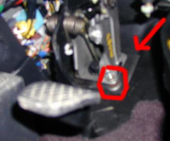
2. Locate clutch switch. This is the upper switch on the clutch pedal assembly, hopefully you got the plug that fits in it, if not you may have to solder some wires to the pins before you install the clutch pedal assembly. Run one of these wires to a good ground source(there should be ground wires visible in the drivers kick panel area) and the other wire will go to the starter relay(it doesn't matter which clutch wire goes to the relay and which goes to ground).
3. Do not worry about cutting the immobilizer wire. Yes the car will crank without the right key, but it still needs the fuel signal to start the car. Cut the lt. blue wire so you have enough coming from the relay so you can work with it comfortably. Cap off the wire that came from the immobilizer and strap it up into the dash out of the way. Now attach the clutch wire to the lt. blue wire with your favorite choice of connectors and such. I used a 18ga butt connector, but in the spring I am going to re-wire and used solder and shrink tube to make it all clean looking.
You should now be able to start the car only when the clutch pedal is fully depressed. You may have to adjust the switch in or out to have it make full contact and work properly. If it doesn't work and you have adjusted the pedal, try to make sure you have a good solid ground on the (-)clutch switch wire.
"Back Up" Lights
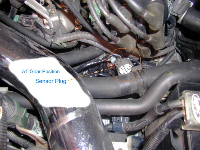
Now lets move on to "back-up" lights or the reverse lights as they are properly termed. On the AT there was a connector you removed that is called the AT Gear Position Sensor Plug. This told the auto ECU, and other parts in your car, which gear you where in. We need to be able to tell these parts when you put the car in reverse. It would be nice if the plug on the 5 speed tranny matched up, but its not that easy. The manual has a 2 wire switch that is mounted in the tranny and just has a couple wires hanging out. It has bullet style connectors on it which you could easily connect to with the right mating bullet connectors. I opted to hardwire new wires on so I could extend them, making it easier to patch into the Gear Position Sensor Plug.
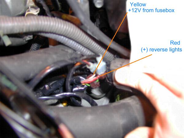
It would have been nice if Honda could have at least used the same color wires for the reverse hookup. The right colors are there, but don't use them cause they are not what you think, I tried. You will have to hook one of the reverse switches wires to the yellow wire on the harness and the other to the red wire on the harness. The yellow provides a +12Volt input when your ignition switch is on, and the red wire send that power to the reverse lights. Polarity doesn't matter so hook which ever wire you want from the switch into either on the harness.
Cruise Control
While not a necessity (your cruise will work without this), it is a good idea to wire the clutch to the cruise so if you push the clutch with the cruise on you wont peg the rpms on your engine till you hit the brake or cancel button. It is quite simple.
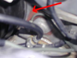
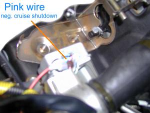
The cruise control module is mounted right next to the steering column as shown below in my fuzzy pic. It is a small silver box with one plug on it(gray I think). You will find a pink wire in the harness, use some sort of tap to hook into this wire but leave it connected to the box. The switch on the front of the clutch pedal assembly(the part closest to the driver), is the switch for canceling the cruise. Again if you don't have the plug just solder wires to the pins. Run one wire to good ground(just use same as first switch) then run the other to the cruise control box. Now you can test it by driving your car, setting the cruise and lightly touch the clutch, it should shutdown with just by resting your foot on the pedal and taking up the free play, if not adjust the switch in or out so it does. When testing be prepared to hit your cancel button, just in case it doesn't shut down right away.
* Main write up taken from Mazmo. Revisions done by Infamouz
Disclaimer: All information on this website is to be used as a REFERENCE ONLY. Canadian Prelude Club and I take no responsibility what so ever for problems that may occur for those who use and apply this information. Also, this information is specific to the 5th Generation Honda Prelude (1997 to 2001) and may not apply to all the model years. Informational purposes only, means just that.
List of Parts:
- Helms Manual [VERY IMPORTANT] - You can download it by clicking here
- Transmissions Assembly (97+)
- Trans mounts-side
- Engine Mount-rear (rear is optional-the rear auto mount will work)
- Flywheel and bolts
- Clutch Kit and bolts
- Clutch Master Cylinder
- Clutch Slave Cylinder*
- Clutch Dampener*
- Vehicle Speed Sensor (VSS)*
- Reverse Switch*
- Hydraulic Lines*
- 5spd Starter*
- Clutch Pedal Assembly
- Brake Pedal Assembly
- Shifter Assembly
- Shift linkage
- Auto ECU or 5speed ECU
- 5spd Intermediate shaft (half-shaft)
- 5spd Gauge Cluster (optional)
- Cotter Pins (assorted sizes)
- Shifter Boot
- Shifter Knob
- Throw-out Bearing
- Pilot Bearing
* MOST LIKELY THESE WILL BE ATTACHED TO TRANNY (DOUBLE CHECK)
**This list of parts consists of the main components needed and does not include every little nut, bolt, and bracket. You get the idea.
Where to start?
Make sure you have a lot of metric wrenches, sockets (short and deep), various ratchets (1/4, 1/2, 3/8), and a good torque wrench, If you don't have access to a vehicle lift, I would suggest you find one or be prepared for a struggle. I will also include the necessary wiring diagrams we created to get the car running. It is a good idea to find all the pages of the Helms that you will be using and place post-its at the top.
Auto Transmission Removal Tips
The Helms is good tool and give a protocol to the dismantling process. Start on page 14-125 and continue to do so until you reach page 14-127. Here you have two options. The first is to follow the book, but if you are having trouble separating the lower arm like I did, you can unfasten the sway bar, radius rods, and take the damper fork bolts out. This will allow you enough swing to remove the axles. If you don't have a good ball joint remover, I recommend using our method. . We tried two of the Pitman Pullers with no luck. I actual ripped a seal trying. If you can't get the Honda tool listed in the Helms, just use the method we figured out. Now you are back to following the Helms, but the Helms only take you so far. The book doesn't expect you to swap trannies. With the tranny out you can now get the shift cable out and put the new 5spd one in. This looks tricky at first because it looks like you may have to drop your exhaust to get access, but it will unbolt with a little creativity. (my header and cat bolts are so rusted we would of had to cut them off) The space it tight, but one you undo the heatshield protecting the cable, you can unbolt the plate holding the cable in place and be glad you didn't have to take the exhaust off to gain access. You can use page 14-204 for a reference. At this point you might as well put the replacement 5spd cables in place. The great thing about this swap is 99% bolts right up and a lot of the nuts and bolt can be reused..
Manual Transmission Installation Tips
Page 12-3 is a good reference page to stick a bookmark in. Start with pages 12-8 to 12-11 to get you started. This will cover the flywheel and clutch installation. When tightening up the flywheel and clutch, the Helms shows this being done using a ring gear holder (Honda tool). We did not have this tool so we just held the crank in place from the other side (located in driver side wheel well) with a breaker style wrench. Now you will skip to page 13-10 to start the installation of the trans. You will continue from that page until the book tells you to reverse the order of the removal instructions. At this point read up on the instructions and get used to reading the steps in reverse and figuring out how to apply them properly. Continue to read/install the tranny and you will notice on page 13-7 that they removed the lower header pipe. You DO NOT need to remove this pipe. I'm not sure why this is in the book because we had no trouble with it being in place. I honestly don't think we would have been able to remove it without cutting the bolts anyway. Don't forget to run the hydraulic lines. The line as you can see will be very hard to fish through all the stuff in your engine compartment. We go a little creative and ran it where ever it fit the best. We used a line bender to help us reroute it. It basically your call on how you should run the lines, but make sure you don't kink the line too much. I used zip-ties to fasten the hydraulic line to various point.
Clutch Master Cylinder Installation / Fabrication Tips
This can get tricky because this is where you start hacking up your car. Page 12-5 will give some pointers. Either find someone with a Prelude to use as a guide or just guestimate. The easiest way to mount the master cylinder is to make a template out of cardboard so you can easily make your marks before you drill. What you can do is take your clutch pedal and hold it up to about where you "think" you want it and and make some marks. I also recommend making two plates from 18 Gauge steel to help stiffen the weak firewall. This will help make the clutch pedal sturdy because when doing a swap, you will most likely not have a bracket to help hold the clutch pedal up. These plates are real easy to make. Just cut them a little bigger than your master cylinder template (that you made earlier), but not so big that they will not mount flush against the firewall (you will get my point when you start doing it). Just put one plate on the outside (against firewall) and the other inside the passenger compartment against the firewall. Now you can mount the clutch pedal. It will bolt right on the the backside of the master cylinder.
Clutch Pedal and Brake Pedal Installation Tips
This section is very Important
Remove the old brake pedal assembly and put the 5spd specific one in its place. Hook up the brake switch and make sure it works properly. Used page 19-5 for pointers. I've heard that some people cut their brake pedal, but I DO NOT recommend it. Installation of the clutch pedal may be easier if you have the brake pedal off at that time. Its up to you and how well you work in tight spaces.
Time to mount the clutch pedal. Its is best to have a helper present to hold the master cylinder while you tighten down the nuts. Before you start tightening, you need to check to see if your clutch pedal assembly came with spacers SEE PIC BELOW. Most likely they will not, but you may get lucky. These spacers are located behind the pedal assembly against the firewall. My pedal did not come with these spacers and we did not know that they even existed at first. My clutch was slipping more and more as the car warmed up, but would stop slipping if cooled down by driving on the highway. This was real confusing and time consuming considering we had not idea what the problem was. After a quick inspection of my friends Prelude, I noticed the spacers. Problem solved. I obviously did not have the spacers, so I looked around for something the same size. Luckily the self locking nuts that I removed from the damper forks (page 13-8 show a good pic) worked. You are supposed to replace these anyway, so we got lucky. What we did was position the master cylinder with the two fabricated plates in place, put the two nuts on (with the flat side against the plate), and a washer to the side closest to the passenger compartment. Now just tighten everything up and make your adjustments using page 12-4 and 12-5 as a reference. There may be some trouble shooting involved to make your clutch operate properly. Depending on your application and fabrication pieces, you may need to add/remove washers to the backside of your clutch pedal assembly to get the proper pedal rod movement. The best way to test your spacer set-up is to do some city style driving (stop and go) and stay away form the highway because it will cool off your clutch and cause it not to slip. Luckily we got it right on the first try, buy you may need to add/remove accordingly. Remember that every time you make changes to your pedal, you will need to make the proper adjustments found on page 12-4.
Bleeding the Clutch System
Now that you have everything together the clutch lines will be bone dry. We tried to bleed the conventional way for quite some time without luck. You need a vacuum bleeder to pull the fluid through the system. You will thank yourself.
Shift Assembly and Gauge Cluster Removal / Installation
Use page 20-45 to aid in the removal of your center console. You can now remove all the automatic shifter assembly and related items. Now just bolt up your new gear shift mechanism using page 13-13 as a reference. Replacing the gauge cluster is just as easy, as well as optional. The auto cluster will work just fine. The 5spd cluster is plug-in-play (minus the plug for the gear selection). First, remove the two screws holding the trim piece in place, then pry the panel working gently because you don't want to mark it up. Now you have access to to the actual cluster. Use page 23-65 for reference.
Wiring and Computer Related Issues
You can use your auto ECU if you like (NOT RECOMMENDED) and do some creative wiring to get rid of the check engine light. There will be some idling issues (randomly pulsing idle) but the check engine light will not be on. Page 11-4 will give you an idea of where the components are. Follow the instructions closely starting on page 23-195. I did run the auto ECU for a while, but have since gone to a Honda dealer to have the 5spd ECU programmed with my immobilizer code and it works great!
Comment from Infamouz:
Whether you are going to proceed using your current AUTO ECU or exchange it for a MANUAL ECU, either unhook the connectors from your TCM (Transmission Control Module) or remove the entire module. (pics to come)
The most cost efficient way to come about this procedure is to use your existing AUTO ECU and re-solder the resistor from RP13 to RP14. If you're not comfortable with electrical work, please have a professional do it instead.
The safest way (avoiding a headache) is to use a MANUAL ECU. Since the 5th gen preludes have immobilizers, randomly connecting an ECU from another car is not going to work. YOU WILL NEED THE ECU AND THE RESPECTIVE RED LEARNING KEY. You would have to then take it to Honda or a professional to reprogram the ECU to match your vehicle's immobilizer code.
Wiring for Prelude Auto Trans to 5 Speed Tranny Swap
Clutch/ Starter Switch
First and most important mod is to stop your lude from being started while the clutch is engaged, cause you might launch it through your garage wall. Luckily Honda has provide a very easy way to kill the starter. Your "immobilizer" sends a signal to this starter relay, to allow power to pass to the starter. We will be using the clutch switch to provide this signal instead.
1. Locate the starter relay under the dash. My pic is fussy cause the camera doesn't focus good up close. You should find it on the back side of the dash panel below the steering column, the relay is positioned just about in-line with the clutch pedal, and the plug is facing down. It is easily identifiable by the large gauge wires it uses. It has two 10ga white/red stripe, one 10ga black/white stripe, and one 18ga(maybe 22ga) light blue wires. The white/reds come from the ignition switch and this is where the starter gets the power. The black/white is the wire connected to the starter to make it kick on, and the lt. blue is the ground signal that the immobilizer sends out.
2. Locate clutch switch. This is the upper switch on the clutch pedal assembly, hopefully you got the plug that fits in it, if not you may have to solder some wires to the pins before you install the clutch pedal assembly. Run one of these wires to a good ground source(there should be ground wires visible in the drivers kick panel area) and the other wire will go to the starter relay(it doesn't matter which clutch wire goes to the relay and which goes to ground).
3. Do not worry about cutting the immobilizer wire. Yes the car will crank without the right key, but it still needs the fuel signal to start the car. Cut the lt. blue wire so you have enough coming from the relay so you can work with it comfortably. Cap off the wire that came from the immobilizer and strap it up into the dash out of the way. Now attach the clutch wire to the lt. blue wire with your favorite choice of connectors and such. I used a 18ga butt connector, but in the spring I am going to re-wire and used solder and shrink tube to make it all clean looking.
You should now be able to start the car only when the clutch pedal is fully depressed. You may have to adjust the switch in or out to have it make full contact and work properly. If it doesn't work and you have adjusted the pedal, try to make sure you have a good solid ground on the (-)clutch switch wire.
"Back Up" Lights
Now lets move on to "back-up" lights or the reverse lights as they are properly termed. On the AT there was a connector you removed that is called the AT Gear Position Sensor Plug. This told the auto ECU, and other parts in your car, which gear you where in. We need to be able to tell these parts when you put the car in reverse. It would be nice if the plug on the 5 speed tranny matched up, but its not that easy. The manual has a 2 wire switch that is mounted in the tranny and just has a couple wires hanging out. It has bullet style connectors on it which you could easily connect to with the right mating bullet connectors. I opted to hardwire new wires on so I could extend them, making it easier to patch into the Gear Position Sensor Plug.
It would have been nice if Honda could have at least used the same color wires for the reverse hookup. The right colors are there, but don't use them cause they are not what you think, I tried. You will have to hook one of the reverse switches wires to the yellow wire on the harness and the other to the red wire on the harness. The yellow provides a +12Volt input when your ignition switch is on, and the red wire send that power to the reverse lights. Polarity doesn't matter so hook which ever wire you want from the switch into either on the harness.
Cruise Control
While not a necessity (your cruise will work without this), it is a good idea to wire the clutch to the cruise so if you push the clutch with the cruise on you wont peg the rpms on your engine till you hit the brake or cancel button. It is quite simple.
The cruise control module is mounted right next to the steering column as shown below in my fuzzy pic. It is a small silver box with one plug on it(gray I think). You will find a pink wire in the harness, use some sort of tap to hook into this wire but leave it connected to the box. The switch on the front of the clutch pedal assembly(the part closest to the driver), is the switch for canceling the cruise. Again if you don't have the plug just solder wires to the pins. Run one wire to good ground(just use same as first switch) then run the other to the cruise control box. Now you can test it by driving your car, setting the cruise and lightly touch the clutch, it should shutdown with just by resting your foot on the pedal and taking up the free play, if not adjust the switch in or out so it does. When testing be prepared to hit your cancel button, just in case it doesn't shut down right away.
* Main write up taken from Mazmo. Revisions done by Infamouz