HOW TO: H22A VALVE ADJUSTMENT


HOW TO: H22A VALVE ADJUSTMENT
Disclaimer: I am not a professional. Any and all happenings good or bad are completely up to the user of this DIY write up. This is exactly what I did on my 2000 SH and it worked great. If you so choose to use this write up, Canadian Prelude Club or I am in no way responsible for any outcome that may occur.
Tools required:
VERY IMPORTANT:
Make sure that your engine is cold. I let my car sit for just over three hours before starting. I had only driven it 5 miles to the shop. When I began removing parts it was still too warm to do the adjustment. I would suggest that if it isnt cold, not luke warm but cold, that you do not do this procedure. Wait until it is cold.
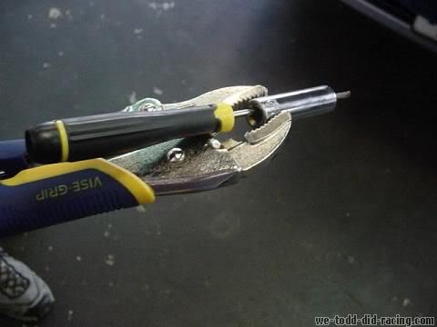
Snap-on corp makes a tool specifically for honda. This tool is used for valve adjustments and valve adjustments only. I did not use this tool. I made my own. If you would like to it is easy. All you will need is a pair of Vise-grips, a 10mm deep well socket, and a flat head screwdriver that will fit through the hole of the socket.
Angle the vice grips at apx. 80 degrees when you clamp it to the 10mm socket. Stick the screw driver through the socket and there you go. You just scarred up a perfectly good socket but saved $40.
PROCEDURE:
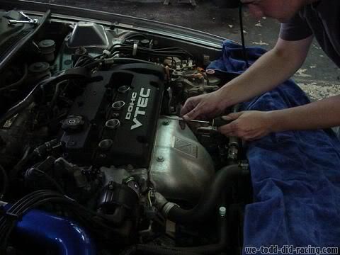
-start by removing the spark plug cover. Use the 10mm socket for this.
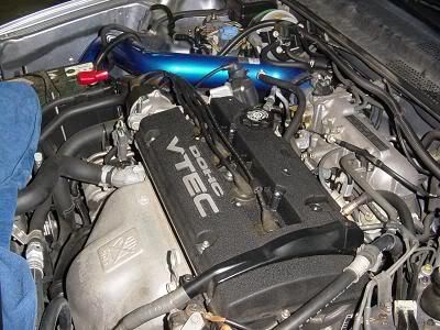
- remove the spark plug wires and place them off to the side. Make sure to keep the terminals clean.
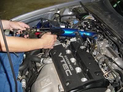
- the alternator wires run along top of the valve cover and will need to be removed. Start by taking off the bolt attatching the wire harness to the front of the valve cover. Once again using the 10mm socket.
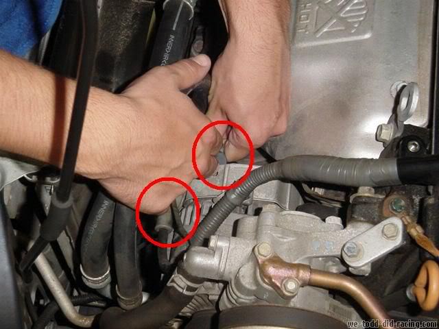
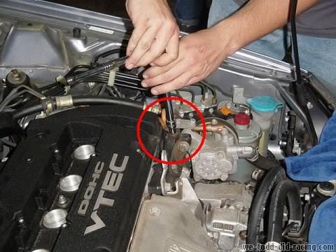
- next remove the plug and nut on the alternator. The plug has one snap on it and the nit is also a 10mm. You may want to pull back the rubber cover to get better access to it.
- the wiring harness has a plastic clip attaching it as well. You can use your hand to pull it off or a small flat head screw driver to pry it off.
- finally for the wiring harness remove the upper bolt. Attached to the rear of the valve cover. Use the 10mm socket for this.
- once you have removed all attaching hardware for the wiring harness carefully lift and place behind the engine ontop of the intake manifold.
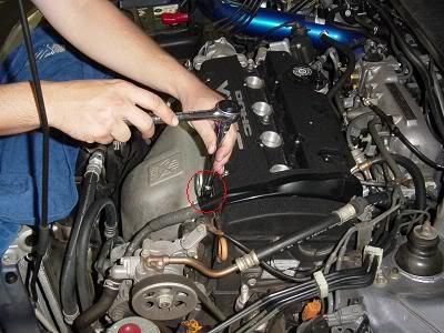
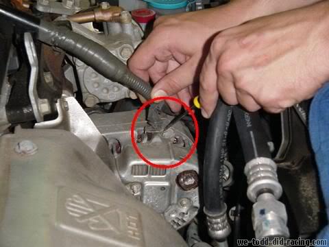
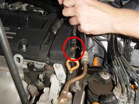
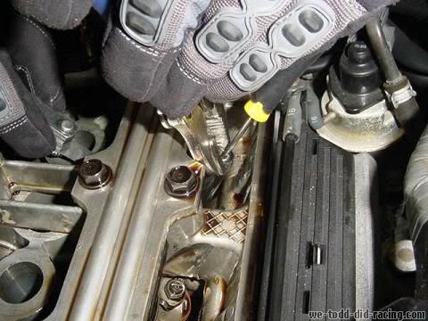
- next there is a ground wire that will need to be removed. This is on the drivers side of the car and will use the 10mm socket.
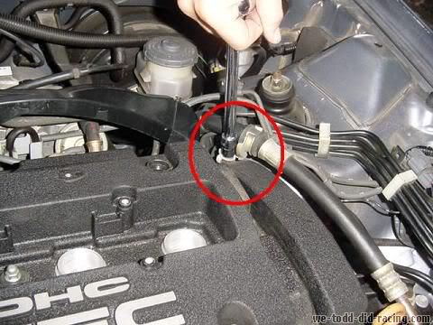
- there is another grounding strap that will need to be removed. It is in the close proximity to the one just removed. It will use the 10mm socket as well
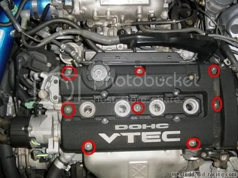
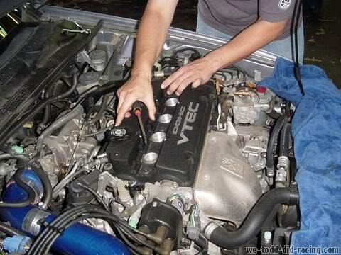
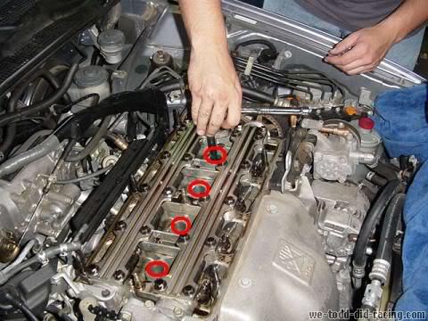
- On to the Valve cover. There are 8 round top nuts that will need to be removed.
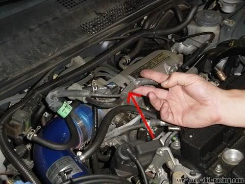
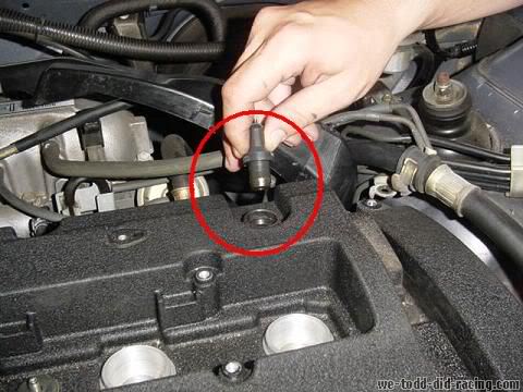
- next remove the PVC plug
- there is only one hose left. That will be going from your intake to the valve cover. I did not get a picture of it but depending on the type of clamp you have there you will want to use either a socket, flat head screwdriver, or a pair of pliers.
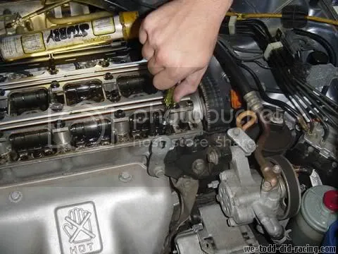
- now you are ready to remove the valve cover. Place your flat head screwdriver in between the head and the valve cover. Gently pry it loose. If you are careful you will be able to reuse the same seal over and over again. Just remember to re oil it before replacing.
- once the valve cover is loose you can remove it. Do not set it down on its seal. Place it seal up to keep it clean and free of debris.
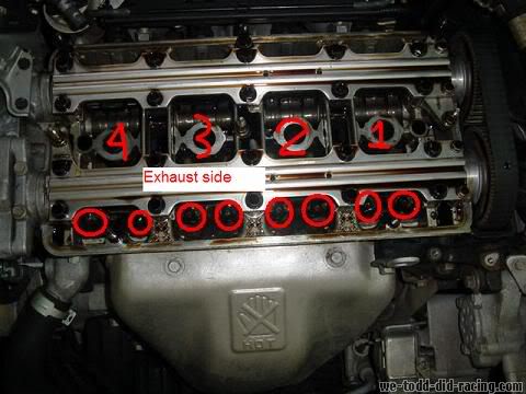
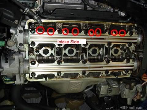
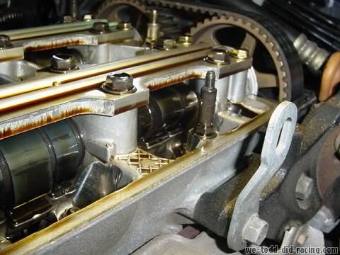
- now you should be looking at the top of your head. On the exhaust manifold/header side is the exhaust cam. The intake manifold side is the intake cam. There are 8 valves per side. 16 total. Each valve has a set screw/lock nut which you will use your special tool or wrench and screw driver and torque wrench to adjust.
- Now it is time to remove the spark plugs. You do not have to but it does help to relieve pressure in the engine and I would highly suggest it.
- go to each valve and loosen the lock nuts. Use a 10mm socket for this.
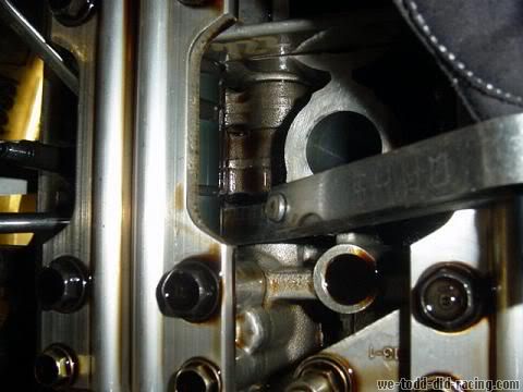
- while doing this adjustment it is very important that the valves be closed. To make certian that they are closed set the cam you are working on to show the lobe looking at you.
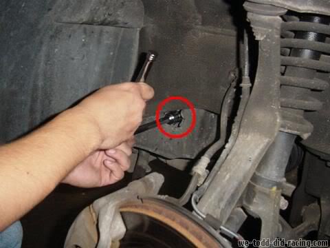
To do this you will need to turn the crank manually. Remove the drivers side front tire and you will see a hole. It is just big enough to place your 19mm socket in. You will need the 6'' extention for this. Turn the crank COUNTER CLOCKWISE. It may take some brute force at times, just remember what you are turning. Its not light weight so put your shoulder into it. Stop when you can see that the lobe is facing any direction but down or at a downward angle. You will need to repeat this step for each set of valves. Both intake and exhaust. It does get tedious but it is precise.
- now it is time to start the actual adjustment. To do the actual adjustment you will need to use your feeler gauge and your ghetto fab tool or wrench and screwdriver. Unless you spent the $40 on the correct tool. You should feel drag on the feeler gauge when it is at the correct setting. Move the feeler gauge in and out while your shop partner tightens/loosens the set screw. When it gets tight but still movable set the locknut. Make sure that when you have the correct valve lash set that you do NOT move the screwdriver at all while you tighten the locknut.
The way that I made sure that I had the correct ammount of play was to use the low side. As an example on the intake side I used the .006 for the setting. When I felt that I had it correct we would set the locknut. I would then take the .007 and check to make sure it did not fit in. If the .006 fit and the .007 did not we would torque the locknut to 14 lb ft and then check again. If nothing moved we moved to the next valve. You may have to repeat this multiple times per valve to get it just right.
Once you have completed the adjustment go over everything once again. Check all lash clearances to make sure nothing has moved. If it did; redo it.
Once everything is set and good to go replace all parts in reverse order.your car should be withing specs now and running smoother.
Hope this helped. if anyone has any additions/corrections please let me know.
--------
Courtesy: Shakes via HondaTech
Tools required:
- 10mm deep well socket
- 10mm wrench
- 19mm deep well socket
- Spark plug socket
- 6" extension
- Ratchet
- Vise grips (optional. I used them)
- Medium Flat tip screw driver
- Pliers (depending on what type of clamps you have on your hoses going to the valve cover)
- Torque wrench (14 lb ft or 168 lb in )
- Angled feeler gauge (.006, .007, .008) For those that need further explanation .005 is intake low; .006 is intake high; .007 is exhaust low; .008 is exhaust high. recommend using .006 for intake, .007 to check, and .008 for exhaust with .009 to check
- Friends to help
VERY IMPORTANT:
Make sure that your engine is cold. I let my car sit for just over three hours before starting. I had only driven it 5 miles to the shop. When I began removing parts it was still too warm to do the adjustment. I would suggest that if it isnt cold, not luke warm but cold, that you do not do this procedure. Wait until it is cold.
Snap-on corp makes a tool specifically for honda. This tool is used for valve adjustments and valve adjustments only. I did not use this tool. I made my own. If you would like to it is easy. All you will need is a pair of Vise-grips, a 10mm deep well socket, and a flat head screwdriver that will fit through the hole of the socket.
Angle the vice grips at apx. 80 degrees when you clamp it to the 10mm socket. Stick the screw driver through the socket and there you go. You just scarred up a perfectly good socket but saved $40.
PROCEDURE:
-start by removing the spark plug cover. Use the 10mm socket for this.
- remove the spark plug wires and place them off to the side. Make sure to keep the terminals clean.
- the alternator wires run along top of the valve cover and will need to be removed. Start by taking off the bolt attatching the wire harness to the front of the valve cover. Once again using the 10mm socket.
- next remove the plug and nut on the alternator. The plug has one snap on it and the nit is also a 10mm. You may want to pull back the rubber cover to get better access to it.
- the wiring harness has a plastic clip attaching it as well. You can use your hand to pull it off or a small flat head screw driver to pry it off.
- finally for the wiring harness remove the upper bolt. Attached to the rear of the valve cover. Use the 10mm socket for this.
- once you have removed all attaching hardware for the wiring harness carefully lift and place behind the engine ontop of the intake manifold.
- next there is a ground wire that will need to be removed. This is on the drivers side of the car and will use the 10mm socket.
- there is another grounding strap that will need to be removed. It is in the close proximity to the one just removed. It will use the 10mm socket as well
- On to the Valve cover. There are 8 round top nuts that will need to be removed.
- next remove the PVC plug
- there is only one hose left. That will be going from your intake to the valve cover. I did not get a picture of it but depending on the type of clamp you have there you will want to use either a socket, flat head screwdriver, or a pair of pliers.
- now you are ready to remove the valve cover. Place your flat head screwdriver in between the head and the valve cover. Gently pry it loose. If you are careful you will be able to reuse the same seal over and over again. Just remember to re oil it before replacing.
- once the valve cover is loose you can remove it. Do not set it down on its seal. Place it seal up to keep it clean and free of debris.
- now you should be looking at the top of your head. On the exhaust manifold/header side is the exhaust cam. The intake manifold side is the intake cam. There are 8 valves per side. 16 total. Each valve has a set screw/lock nut which you will use your special tool or wrench and screw driver and torque wrench to adjust.
- Now it is time to remove the spark plugs. You do not have to but it does help to relieve pressure in the engine and I would highly suggest it.
- go to each valve and loosen the lock nuts. Use a 10mm socket for this.
- while doing this adjustment it is very important that the valves be closed. To make certian that they are closed set the cam you are working on to show the lobe looking at you.
To do this you will need to turn the crank manually. Remove the drivers side front tire and you will see a hole. It is just big enough to place your 19mm socket in. You will need the 6'' extention for this. Turn the crank COUNTER CLOCKWISE. It may take some brute force at times, just remember what you are turning. Its not light weight so put your shoulder into it. Stop when you can see that the lobe is facing any direction but down or at a downward angle. You will need to repeat this step for each set of valves. Both intake and exhaust. It does get tedious but it is precise.
- now it is time to start the actual adjustment. To do the actual adjustment you will need to use your feeler gauge and your ghetto fab tool or wrench and screwdriver. Unless you spent the $40 on the correct tool. You should feel drag on the feeler gauge when it is at the correct setting. Move the feeler gauge in and out while your shop partner tightens/loosens the set screw. When it gets tight but still movable set the locknut. Make sure that when you have the correct valve lash set that you do NOT move the screwdriver at all while you tighten the locknut.
The way that I made sure that I had the correct ammount of play was to use the low side. As an example on the intake side I used the .006 for the setting. When I felt that I had it correct we would set the locknut. I would then take the .007 and check to make sure it did not fit in. If the .006 fit and the .007 did not we would torque the locknut to 14 lb ft and then check again. If nothing moved we moved to the next valve. You may have to repeat this multiple times per valve to get it just right.
Once you have completed the adjustment go over everything once again. Check all lash clearances to make sure nothing has moved. If it did; redo it.
Once everything is set and good to go replace all parts in reverse order.your car should be withing specs now and running smoother.
Hope this helped. if anyone has any additions/corrections please let me know.
--------
Courtesy: Shakes via HondaTech

.
In a world full of copies, be an original.
.
Graphic Design: Indezyne | Rare Prelude Parts: InfamouzJDM