HOW TO: Install JDM Climate Control (4th Gen)
HOW TO: Install JDM Climate Control (4th Gen)
Disclaimer: All information on this website is to be used as a REFERENCE ONLY. Canadian Prelude Club and I take no responsibility what so ever for problems that may occur for those who use and apply this information. Also, this information is specific to the 4th Generation Honda Prelude (1992 to 1996) and may not apply to all the model years. Informational purposes only, means just that.
Write-up by: Forbidden via AbsolutePrelude
Written on: 25/07/2002
Last Updated: 18/09/2003
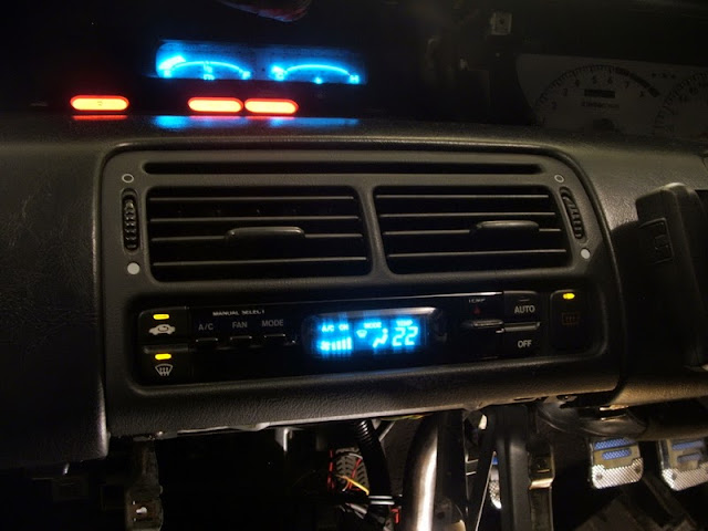
* Picture courtesy of Street_Lude
Table of Content:
Introduction
Parts
Tools
Disassembling
Wiring
Assembling
Conclusion
Resources
Well this is it, I'm planning on making this THE guide on how to install a JDM Climate Control in a 4th gen USDM Prelude. I'll try to cover all aspect of this install, what parts you need and how to hook them up. I won't explain how to remove your consoles and stuff like that (not for now anyway), you should have a Helm handy at all time when working on your car. Also please note that I am not responsible if you blow up your car, get a fine for releasing freon in the atmosphere or any other injuries or whatever that could happen.
Parts
Here are the parts you'll need to get a fully functional JDM Climate Control. (pictures courtesy of Street_Lude)
For the Power Transistor, I used one from a 1st gen Acura CL. It's part number is 79330-SF1-941. For the Blower Motor High Relay I used a fog light relay and sub-harness for the Prelude but when I received it there was no sub-harness cause it has been discontinued. So you can probably find a relay that'll work at a scrap yard or something so you have a connector with it. For the Air Mix Control Motor I tried one from an Accord but it doesn't work very well, I only have full hot or full cold, nothing in between, so I'm ordering a JDM air mix motor, For the Heater Valve and Solenoid you could use the manual heater valve you already have in your car but I decided to get a JDM vacuum actuated heater valve to make my conversion more JDM style.
Tools
Well you'll need a few tools to install the Climate Control. You'll probably have most tools you'll need if you've done any work on your car already.
You're gonna have to do a lot of disassembling. I'm not gonna go into details about how to disassemble all that stuff, you really should have a Helm before trying a project like this one.
Since I did this spanned over a year because I didn't have all the parts I needed and stuff, I disassembled and re-assembled this stuff a few times but for this write-up I'll write it so that you can do it in a weekend or so.
Center console removal
First remove your front console where the shifter is, then remove the center panel where the stereo and cig lighter is. Now you can remove the heater control panel and center air vent. It should now look like this.
Dash removal
Now remove the glove box, the dashboard lower cover, the knee bolster, the tweeter covers, the viser trim panel and the display visor. Remove the 2 screws under the steering wheel, and disconnect the air bag and connect the red connector. Remove the steering column covers and the air duck under the steering colomn. You can now remove the 2 nuts and 2 bolts that hold the steering and steering column in place and lower the steering on the floor. If you have a passenger side airbag disconnect it and put the red connector on it. Disconnect the 3 connectors on the driver side near the fusebox and the 2 connectors on the passenger side. You can now remove the 6 bolts and remove the dash. Be careful when you get it out of the car so you don't hit anything.
Evaporator removal (A/C equipped cars)
With the dash out of the way, removing the evaporator is quite easy. First make sure you get your A/C system emptied by a professional. Releasing Freon in the atmosphere is illegal and you might be able to get a few bucks if you have a 92 with R-12 in it. Now there's 1 nut and 1 bolt you need to remove under the hood, then there's 5 bolts and 2 nuts inside the car. Disconnect the A/C thermostat and you can pull the evaporator out. Be careful when you pull the evaporator out not to break the pipes, there's one that you'll have to lift up a bit to be able to pull the evaporator.
Here's one of the bolt for the evaporator under the hood.
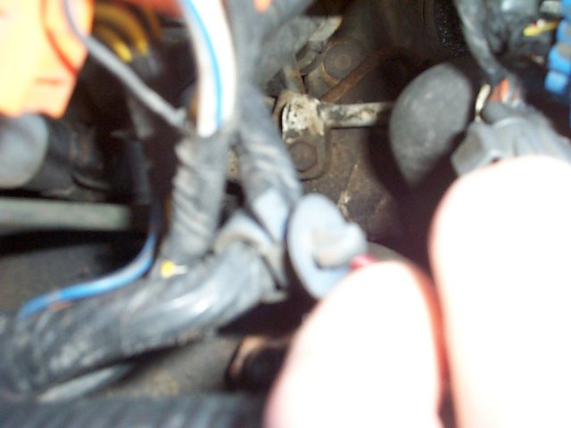
And that's the second bolt for the evaporator under the hood.
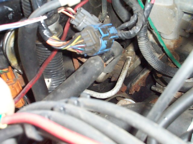
The evaporator is removed.
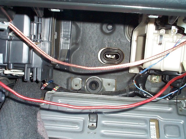
Heater duct removal (Cars without A/C)
Just remove the 4 bolts and remove out of the way.
Blower unit removal
Disconnect the 3 connectors from the blower unit. One's in the from on the blower resistor, the other one on the left side on the recirculation control motor and the 3rd one is under the unit on the blower motor. Now there's 2 bolts and 1 nut to remove and pull out of the way.
Heater unit removal
This one is more tricky, first you'll need to drain the coolant. Then you'll need to remove the intake tube and a few brackets on the firewall. You should remove the bracket holding the MAP sensor and the one under it. Disconnect the heater valve cable from the heater valve and disconnect the 2 coolant hoses that go through the firewall to the heater core. Now a bit below where the hoses where connected and a few inches to each side, there are 2 bolts that pass through the firewall with nuts on them. You'll need a 12mm deep socket to remove them. Remove them, then you can remove the 2 bolts inside the car on top of the heater unit. The one on the driver side is gonna be a bit harder because it's kinda hidden. Now you can pull the heater unit but be careful because there's still coolant inside the heater core and it might spill in your car.
Wiring
Before you begin, to make things easier, don't cut your old connector right off before you start. Cut the wires one by one as you need to cut them to connect another wire to it, that'll save you some trouble as some wires are the same colors.
Powering the unit
Now some wiring, let's start by turning this thing on. When I'll talk about the USDM connector it's the one with 16 pins not the one with the 5 big wires. First connect the No. 8 (BLK/YEL) wire from the UDSM connector to the No. 13 (BLK/YEL) wire on the 20 pin JDM connector. Next connect the ground. There are 2 grounds on the JDM unit, there's the No. 10 (BLK) wire on the 16 pin JDM connector and the No. 16 (BLK) wire on the 20 pin JDM connector. Connect those 2 wires to the No. 13 (BLK) wire on the USDM connector.
At this point the unit should turn on, I didn't actually tried it at that point, I had a few more wires connected. You'll have to press some buttons on it to actually see something on the display. We'll connect the memory soon so you don't have to do that everytime you start the car.
Combination Light Switch and rear window defroster
Now some basic functions, connect the No. 6 (RED/BLK) wire from the USDM connector to the No. 2 (RED/BLK) wire on the 16 pin JDM connector. This is what dims your Climate Control when you turn on the headlight. For the rear window defroster you connect the No. 10 (YEL/WHT) wire from the USDM connector to the No. 14 (YEL/GRN) wire on the JDM 16 pin connector.
Mode Control Motor
For now the unit doesn't do much yet, other than looking cool and turning on the rear window defroster. So let's make it more functionnal. We'll connect the Mode Control Motor to control in which vent the air goes to.
There are 6 wires to connect for this and it's pretty much just cut wire and splice it to the new connector.[/list]
Now we'll hook up the Recirculation Control Motor, there are 2 wires to connect for this. Just like the mode control motor it's pretty much cut and splice back.
Well now that you can control where to blow the air and choose if you want the air from inside or outside of the car, it might be a good idea to actually blow that air out now. There is a bit of wiring to do in order to control the blower. First take a look at this diagram I made. Just in case my diagram isn't clear enough, the square thing on the left is the power transistor and the other one is the blower motor high relay. All wires on this diagrams are wires wou will have to add. The dots on the diagram is where the wires are connected together in the diagram and the numbers are where you'll connect those wires to your car's wiring and JDM Climate Control. The power transistor is what replaces the blower resistors on the blower unit.
Here's what you have to do now:
You should probably make sure all those wires are connected before turning the unit back on. Also make sure you put the power transistor where the blower resistor is in the blower unit because some people blew up their power transistor because it overheated.
Air mix motor
The air mix motor's wiring is pretty easy.
The RED/YEL wire goes to the pin No. 4 on the JDM 16 pin connector.
The RED/WHT wire goes to the pin No. 12 on the JDM 16 pin connector.
The GRY wire goes to the pin No. 7 on the JDM 20 pin connector.
The PNK/BLK wire goes to the pin No. 8 on the JDM 20 pin connector.
The LT GRN/RED goes to a common ground point with the sensors to pin No. 17 on the JDM 20 pin connector.
Sensors
The BRN/RED wire on the In-car temperature sensor goes to pin No. 18 on the JDM 20 pin connector.
The BRN wire on the Evaporator temperature sensor goes to pin No. 9 on the JDM 20 pin connector.
The BRN/WHT wire on the Outside Air temperature sensor goes to pin No. 19 on the JDM 20 pin connector.
The WHT/RED wire on the Sunlight sensor goes to pin No. 10 on the JDM 20 pin connector.
All LT GRN/RED wires goes to a common ground point shared with the air mix motor on pin No. 17 on the JDM 20 pin connector.
Memory
Hook up the wire No. 11 (WHT/YEL) on the JDM 20 pin connector to any wire that always have power to it, even when the car is stop, just like the memory wire on your stereo. You can hook it there if you want, that's where mine is hooked up.
Assembling
Air mix motor
The air mix motor can be a bit complicated to install. If you look at the first picture below, the air mix motor should be in the bottom right corner. In the second and third picture, you can see that the bracket in the JDM cars is almost the same as the USDM bracket except that it's a mirrored copy and instead of a place to connect a cable it's a hole to connect a wire. The problem with the stock location of the air mix motor is this, it's made for a right hand drive car so if you try to mount it like it's mounted on JDM cars, it's gonna work the opposite way. (32 is gonna blow cold air and 18 hot air).
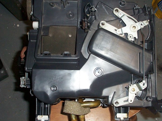
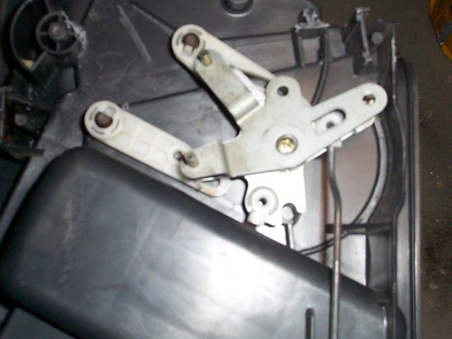
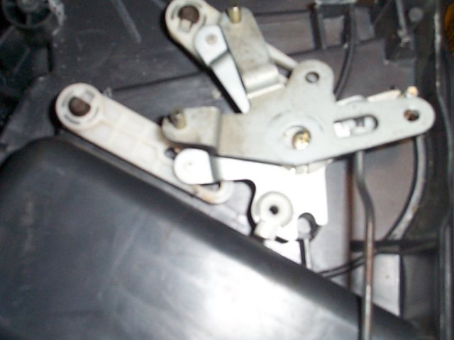
There are a few options to make it work right.
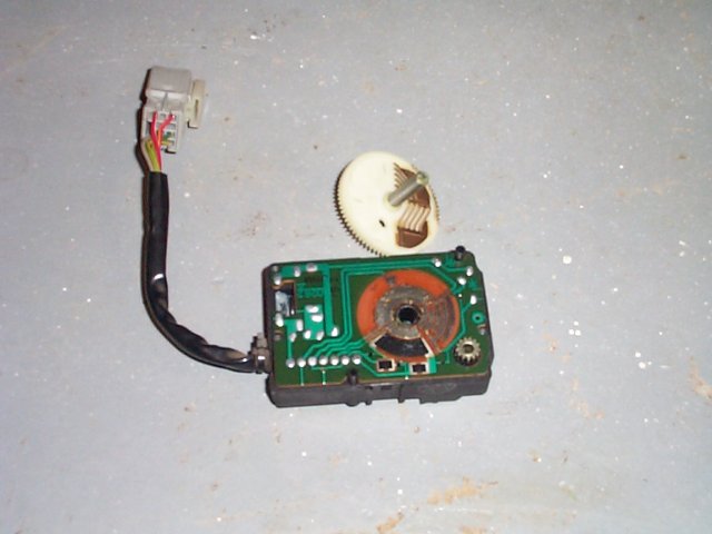
At first I wanted to find a way to mount it in the original location, though if I wanted it to work to right way I would've had to find a way to reverse it. Easier said than done, reversing the hot and cold wire won't work since the motor is gonna send the wrong signal to the unit to tell where it's at. I opened up my air mix motor to see what could be done about it. As you can see in the pictures below, reversing the motor would've require modification to the PCB or maybe even a new PCB that would work the opposite way than the current one. Since I didn't want to be without a car for a month, I decided to go to Plan B.
This is what is looks like without the cover.
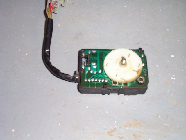
Here I removed the top gear.
The motor under the PCB.
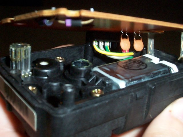
So what's Plan B? Plan B was to find a way to get the air mix motor to work the right way without modifying it. How do you do that? Flip it upside down. The only thing is that you won't be able to mount it in the stock location, so finding another place to mount it is required. Look at the picture below to see how I mounted mine.
Air mix motor mounted to the heater unit.
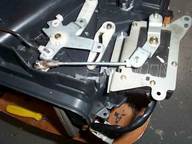
Checking for clearance in the car.
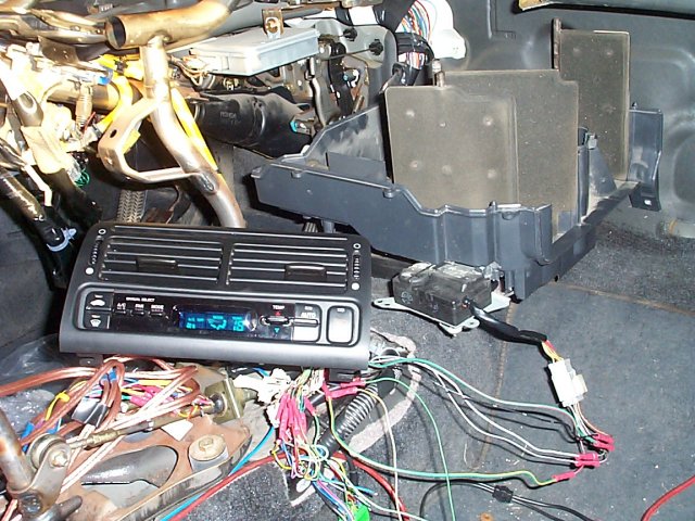
Ready to go back in the car.
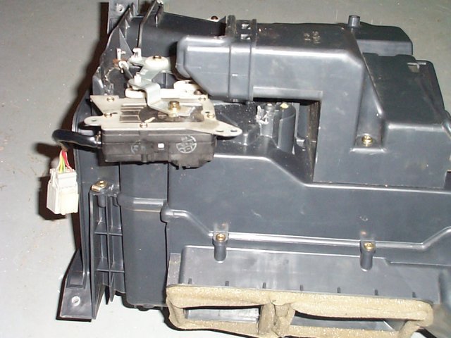
Mounting it this way requires you to take the heater unit appart, take away a bit of plastic that's in the way, drill some holes, put some spacer under the motor bracket and bolt it in place. I used 2 nuts about 3/8" high for the spacer. You'll need a wire to open and close the flaps on the heater so get one the right size and cut and bent where needed. You'll also need some kind of clip or something to connect it to the heater mechanism. Make sure that you set the air mix motor either to full hot or full cold and fully open or close the flaps on the heater depending on either it's full hot or cold when you cut/bent the wire.
Power transistor/Blower motor high relay
The power transistor should go where the blower resistor were and for the blower motor high relay, I just attached it with the bottom screw of the recirculation motor.
Sensors
The In-car temperature sensor goes in the dash between the unit and the steering wheels. You'll need to cut a hole in the dash. For the sunlight sensor, you'll also need to make a hole in the dash but close to the windshield, I made mine on the passenger side a bit but it doesn't really matter where as long as it's close to the windshield. The evaporator sensor goes in the evaporator where the A/C thermostat was. You might need to enlarge the hole in the rubber grommet. The Outside air temperature sensor goes outside to the front of the car, just find a place to mount it near the bumper.


Water valve and solenoid
The water valve just replaces the current water valve in the car on the firewall. It’s attached with one bolt. You’ll need to find a place to mount your solenoid though. And the small vacuum hoses should be hooked up like in this picture with the hose that’s not connected going to the intake manifold if you have a place to connect it. If you don’t have any place left to connect it, you might need to get a T to splice one of the vacuum hose to connect it.
Re-assembling the car
Now re-install your heater unit, blower unit, evaporator, dash and everything else and you should be done! Just make sure you test if everything works before re-installing the dash cause it's not fun to remove and re-install the dash all the time.
Conclusion
Well this is it, the install is finished. I only need to re-fill my A/C system but other than no A/C everything is working great. I hope I haven't forgot anything but if you think I forgot something, let me know. If you have any questions or comments drop me an e-mail at jrc@jrcormier.com
Hope you guys enjoy your fully functional JDM Climate Control!
Resources:
Write-up by: Forbidden via AbsolutePrelude
Written on: 25/07/2002
Last Updated: 18/09/2003

* Picture courtesy of Street_Lude
Table of Content:
Introduction
Parts
Tools
Disassembling
Wiring
Assembling
Conclusion
Resources
Well this is it, I'm planning on making this THE guide on how to install a JDM Climate Control in a 4th gen USDM Prelude. I'll try to cover all aspect of this install, what parts you need and how to hook them up. I won't explain how to remove your consoles and stuff like that (not for now anyway), you should have a Helm handy at all time when working on your car. Also please note that I am not responsible if you blow up your car, get a fine for releasing freon in the atmosphere or any other injuries or whatever that could happen.
Parts
Here are the parts you'll need to get a fully functional JDM Climate Control. (pictures courtesy of Street_Lude)
- Climate Control Unit w/harness (at least the connectors with a few inches of wire)
Probably the best place to get these is on eBay. Or try one of Prelude or Honda board, most of them have some kind of Classify ads section. If you can get everything with the Climate Control Unit, like sensors and the like that's great if not I'll try to give you some hints on where to find the other parts
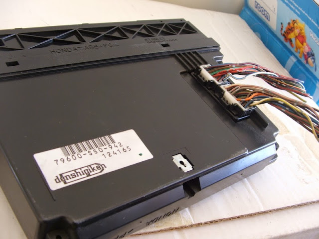
- In-car Temperature Sensor
On the right of the Climate Control Unit, it's a little square vent thing.
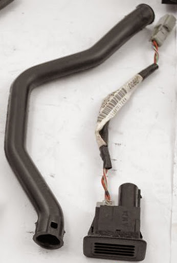
- Outside Air Temperature Sensor
In front of the car, it's in front of the radiator and all that stuff I think.
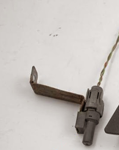
- Sunlight Sensor
On top of the dash near the windshield, it's a little square thing with a round in it.
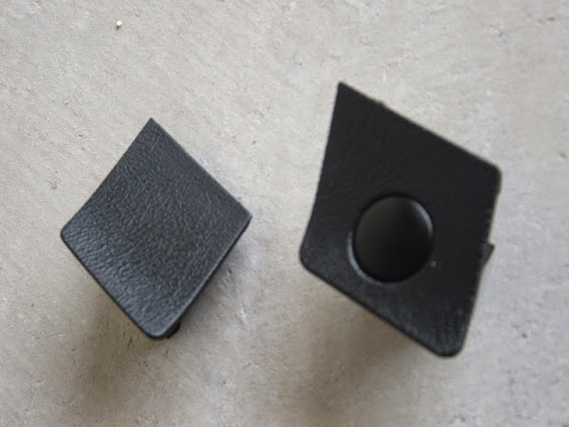
- Evaporator Temperature Sensor
This on is in the evaporator unit, where our A/C thermostat is.
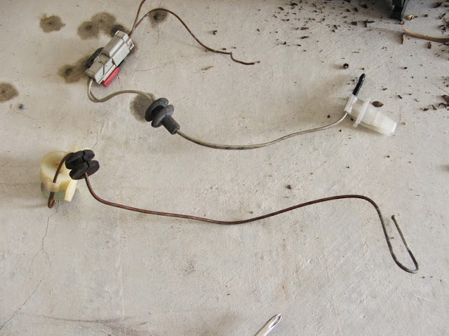
- Air Mix Control Motor
This is under the blower unit.
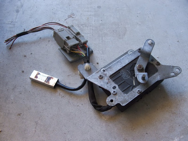
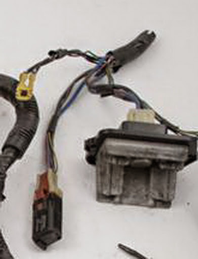
- Blower Motor High Relay
This relay is attached to the blower unit.
- Power Transistor
This is on the blower unit, it's what replaces the blower resistor on our cars.
- Heater Valve and Solenoid (Optional)
This is under your hood, the heater valve is on the water hose that goes from the engine to the heater unit. Try to get the whole system that goes with it.
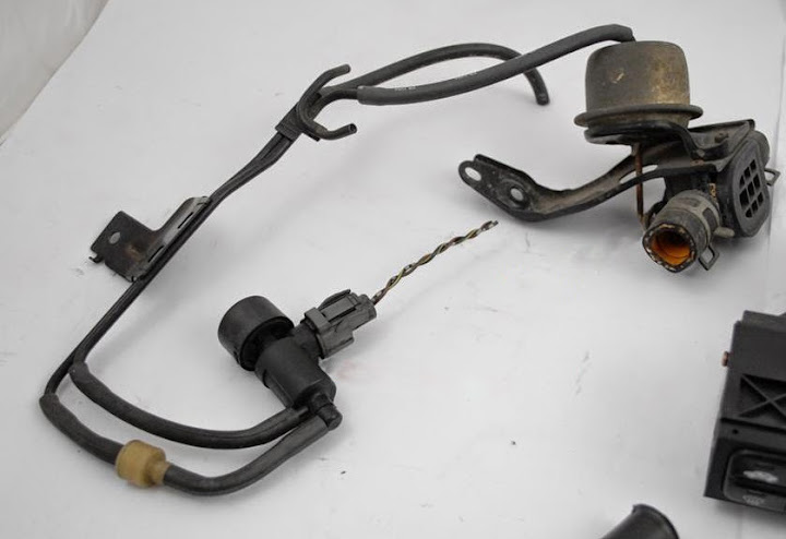
For the Power Transistor, I used one from a 1st gen Acura CL. It's part number is 79330-SF1-941. For the Blower Motor High Relay I used a fog light relay and sub-harness for the Prelude but when I received it there was no sub-harness cause it has been discontinued. So you can probably find a relay that'll work at a scrap yard or something so you have a connector with it. For the Air Mix Control Motor I tried one from an Accord but it doesn't work very well, I only have full hot or full cold, nothing in between, so I'm ordering a JDM air mix motor, For the Heater Valve and Solenoid you could use the manual heater valve you already have in your car but I decided to get a JDM vacuum actuated heater valve to make my conversion more JDM style.
Tools
Well you'll need a few tools to install the Climate Control. You'll probably have most tools you'll need if you've done any work on your car already.
- Helm manual
- Screw drivers (Flat and Philips head)
- Pliers (A few different pairs is a good idea)
- Wire cutters
- Soldering iron or wire crimper
- Set of sockets and wrenches (Other than the ordinary socket set you'll need a 12mm deep socket and also different size extentions will help)
You're gonna have to do a lot of disassembling. I'm not gonna go into details about how to disassemble all that stuff, you really should have a Helm before trying a project like this one.
Since I did this spanned over a year because I didn't have all the parts I needed and stuff, I disassembled and re-assembled this stuff a few times but for this write-up I'll write it so that you can do it in a weekend or so.
Center console removal
First remove your front console where the shifter is, then remove the center panel where the stereo and cig lighter is. Now you can remove the heater control panel and center air vent. It should now look like this.
Dash removal
Now remove the glove box, the dashboard lower cover, the knee bolster, the tweeter covers, the viser trim panel and the display visor. Remove the 2 screws under the steering wheel, and disconnect the air bag and connect the red connector. Remove the steering column covers and the air duck under the steering colomn. You can now remove the 2 nuts and 2 bolts that hold the steering and steering column in place and lower the steering on the floor. If you have a passenger side airbag disconnect it and put the red connector on it. Disconnect the 3 connectors on the driver side near the fusebox and the 2 connectors on the passenger side. You can now remove the 6 bolts and remove the dash. Be careful when you get it out of the car so you don't hit anything.
Evaporator removal (A/C equipped cars)
With the dash out of the way, removing the evaporator is quite easy. First make sure you get your A/C system emptied by a professional. Releasing Freon in the atmosphere is illegal and you might be able to get a few bucks if you have a 92 with R-12 in it. Now there's 1 nut and 1 bolt you need to remove under the hood, then there's 5 bolts and 2 nuts inside the car. Disconnect the A/C thermostat and you can pull the evaporator out. Be careful when you pull the evaporator out not to break the pipes, there's one that you'll have to lift up a bit to be able to pull the evaporator.
Here's one of the bolt for the evaporator under the hood.

And that's the second bolt for the evaporator under the hood.

The evaporator is removed.

Heater duct removal (Cars without A/C)
Just remove the 4 bolts and remove out of the way.
Blower unit removal
Disconnect the 3 connectors from the blower unit. One's in the from on the blower resistor, the other one on the left side on the recirculation control motor and the 3rd one is under the unit on the blower motor. Now there's 2 bolts and 1 nut to remove and pull out of the way.
Heater unit removal
This one is more tricky, first you'll need to drain the coolant. Then you'll need to remove the intake tube and a few brackets on the firewall. You should remove the bracket holding the MAP sensor and the one under it. Disconnect the heater valve cable from the heater valve and disconnect the 2 coolant hoses that go through the firewall to the heater core. Now a bit below where the hoses where connected and a few inches to each side, there are 2 bolts that pass through the firewall with nuts on them. You'll need a 12mm deep socket to remove them. Remove them, then you can remove the 2 bolts inside the car on top of the heater unit. The one on the driver side is gonna be a bit harder because it's kinda hidden. Now you can pull the heater unit but be careful because there's still coolant inside the heater core and it might spill in your car.
Wiring
Before you begin, to make things easier, don't cut your old connector right off before you start. Cut the wires one by one as you need to cut them to connect another wire to it, that'll save you some trouble as some wires are the same colors.
Powering the unit
Now some wiring, let's start by turning this thing on. When I'll talk about the USDM connector it's the one with 16 pins not the one with the 5 big wires. First connect the No. 8 (BLK/YEL) wire from the UDSM connector to the No. 13 (BLK/YEL) wire on the 20 pin JDM connector. Next connect the ground. There are 2 grounds on the JDM unit, there's the No. 10 (BLK) wire on the 16 pin JDM connector and the No. 16 (BLK) wire on the 20 pin JDM connector. Connect those 2 wires to the No. 13 (BLK) wire on the USDM connector.
At this point the unit should turn on, I didn't actually tried it at that point, I had a few more wires connected. You'll have to press some buttons on it to actually see something on the display. We'll connect the memory soon so you don't have to do that everytime you start the car.
Combination Light Switch and rear window defroster
Now some basic functions, connect the No. 6 (RED/BLK) wire from the USDM connector to the No. 2 (RED/BLK) wire on the 16 pin JDM connector. This is what dims your Climate Control when you turn on the headlight. For the rear window defroster you connect the No. 10 (YEL/WHT) wire from the USDM connector to the No. 14 (YEL/GRN) wire on the JDM 16 pin connector.
Mode Control Motor
For now the unit doesn't do much yet, other than looking cool and turning on the rear window defroster. So let's make it more functionnal. We'll connect the Mode Control Motor to control in which vent the air goes to.
There are 6 wires to connect for this and it's pretty much just cut wire and splice it to the new connector.[/list]
- The No. 3 (BRN/WHT) wire from the USDM connector goes to the No. 6 (BRN/WHT) wire on the 16 pin JDM connector
- The No. 7 (LT GRN/WHT) wire on the USDM connector goes to the No. 15 (LT GRN/WHT) wire on the JDM 16 pin connector
- The No. 9 (LT GRN/RED) wire on the USDM connector goes to the No. 15 (LT GRN/RED) wire on the JDM 20 pin connector
- The No. 14 (BLU) wire on the USDM connector goes to the No. 7 (BLU) wire on the JDM 16 pin connector
- The No. 15 (BLU/RED) wire on the USDM connector goes to the No. 8 (BLU/RED) wire on the JDM 16 pin connector
- The No. 16 (YEL/GRN) wire on the USDM connector goes to the No. 16 (YEL/GRN) wire on the JDM 16 pin connector
Now we'll hook up the Recirculation Control Motor, there are 2 wires to connect for this. Just like the mode control motor it's pretty much cut and splice back.
- The No. 4 (GRN/RED) wire from the USDM connector goes to the No. 13 (GRN/RED) wire on the 16 pin JDM connector
- The No. 11 (GRN/WHT) wire from the USDM connector goes to the No. 5 (GRN/WHT) wire on the 16 pin JDM connector
Well now that you can control where to blow the air and choose if you want the air from inside or outside of the car, it might be a good idea to actually blow that air out now. There is a bit of wiring to do in order to control the blower. First take a look at this diagram I made. Just in case my diagram isn't clear enough, the square thing on the left is the power transistor and the other one is the blower motor high relay. All wires on this diagrams are wires wou will have to add. The dots on the diagram is where the wires are connected together in the diagram and the numbers are where you'll connect those wires to your car's wiring and JDM Climate Control. The power transistor is what replaces the blower resistors on the blower unit.
Here's what you have to do now:
- Cut the BLU/RED wire that's connected to the blower motor, you'll have to connect it to the #1 wire on the diagram.
- You will have to splice a wire that comes from the No. 9 fuse in the Under Dash fusebox and connect it to the #2 wire on the diagram. There are plenty of places to splice that wire. I would recommand to use the BLK/YEL wire that connects to the recirculation control motor and attach your relay near the blower unit (that's where the relay is in the JDMs).
- Now connect a wire to the #3 wire on the diagram and to the No. 1 (BLU/RED) wire on the JDM 16 pin connector.
- Connect the #4 wire on the diagram to the No. 3 (BLU/ORN) wire on the JDM 20 pin connector.
- Connect the #5 wire on the diagram to the No. 9 (WHT/BLU) wire on the JDM 16 pin connector.
- And the last but not least #6 wire is connected to a ground anywhere you want.
You should probably make sure all those wires are connected before turning the unit back on. Also make sure you put the power transistor where the blower resistor is in the blower unit because some people blew up their power transistor because it overheated.
Air mix motor
The air mix motor's wiring is pretty easy.
The RED/YEL wire goes to the pin No. 4 on the JDM 16 pin connector.
The RED/WHT wire goes to the pin No. 12 on the JDM 16 pin connector.
The GRY wire goes to the pin No. 7 on the JDM 20 pin connector.
The PNK/BLK wire goes to the pin No. 8 on the JDM 20 pin connector.
The LT GRN/RED goes to a common ground point with the sensors to pin No. 17 on the JDM 20 pin connector.
Sensors
The BRN/RED wire on the In-car temperature sensor goes to pin No. 18 on the JDM 20 pin connector.
The BRN wire on the Evaporator temperature sensor goes to pin No. 9 on the JDM 20 pin connector.
The BRN/WHT wire on the Outside Air temperature sensor goes to pin No. 19 on the JDM 20 pin connector.
The WHT/RED wire on the Sunlight sensor goes to pin No. 10 on the JDM 20 pin connector.
All LT GRN/RED wires goes to a common ground point shared with the air mix motor on pin No. 17 on the JDM 20 pin connector.
Memory
Hook up the wire No. 11 (WHT/YEL) on the JDM 20 pin connector to any wire that always have power to it, even when the car is stop, just like the memory wire on your stereo. You can hook it there if you want, that's where mine is hooked up.
Assembling
Air mix motor
The air mix motor can be a bit complicated to install. If you look at the first picture below, the air mix motor should be in the bottom right corner. In the second and third picture, you can see that the bracket in the JDM cars is almost the same as the USDM bracket except that it's a mirrored copy and instead of a place to connect a cable it's a hole to connect a wire. The problem with the stock location of the air mix motor is this, it's made for a right hand drive car so if you try to mount it like it's mounted on JDM cars, it's gonna work the opposite way. (32 is gonna blow cold air and 18 hot air).


There are a few options to make it work right.
At first I wanted to find a way to mount it in the original location, though if I wanted it to work to right way I would've had to find a way to reverse it. Easier said than done, reversing the hot and cold wire won't work since the motor is gonna send the wrong signal to the unit to tell where it's at. I opened up my air mix motor to see what could be done about it. As you can see in the pictures below, reversing the motor would've require modification to the PCB or maybe even a new PCB that would work the opposite way than the current one. Since I didn't want to be without a car for a month, I decided to go to Plan B.
This is what is looks like without the cover.

Here I removed the top gear.

The motor under the PCB.

So what's Plan B? Plan B was to find a way to get the air mix motor to work the right way without modifying it. How do you do that? Flip it upside down. The only thing is that you won't be able to mount it in the stock location, so finding another place to mount it is required. Look at the picture below to see how I mounted mine.
Air mix motor mounted to the heater unit.

Checking for clearance in the car.

Ready to go back in the car.

Mounting it this way requires you to take the heater unit appart, take away a bit of plastic that's in the way, drill some holes, put some spacer under the motor bracket and bolt it in place. I used 2 nuts about 3/8" high for the spacer. You'll need a wire to open and close the flaps on the heater so get one the right size and cut and bent where needed. You'll also need some kind of clip or something to connect it to the heater mechanism. Make sure that you set the air mix motor either to full hot or full cold and fully open or close the flaps on the heater depending on either it's full hot or cold when you cut/bent the wire.
Power transistor/Blower motor high relay
The power transistor should go where the blower resistor were and for the blower motor high relay, I just attached it with the bottom screw of the recirculation motor.
Sensors
The In-car temperature sensor goes in the dash between the unit and the steering wheels. You'll need to cut a hole in the dash. For the sunlight sensor, you'll also need to make a hole in the dash but close to the windshield, I made mine on the passenger side a bit but it doesn't really matter where as long as it's close to the windshield. The evaporator sensor goes in the evaporator where the A/C thermostat was. You might need to enlarge the hole in the rubber grommet. The Outside air temperature sensor goes outside to the front of the car, just find a place to mount it near the bumper.


Water valve and solenoid
The water valve just replaces the current water valve in the car on the firewall. It’s attached with one bolt. You’ll need to find a place to mount your solenoid though. And the small vacuum hoses should be hooked up like in this picture with the hose that’s not connected going to the intake manifold if you have a place to connect it. If you don’t have any place left to connect it, you might need to get a T to splice one of the vacuum hose to connect it.
Re-assembling the car
Now re-install your heater unit, blower unit, evaporator, dash and everything else and you should be done! Just make sure you test if everything works before re-installing the dash cause it's not fun to remove and re-install the dash all the time.
Conclusion
Well this is it, the install is finished. I only need to re-fill my A/C system but other than no A/C everything is working great. I hope I haven't forgot anything but if you think I forgot something, let me know. If you have any questions or comments drop me an e-mail at jrc@jrcormier.com
Hope you guys enjoy your fully functional JDM Climate Control!
Resources:

.
In a world full of copies, be an original.
.
Graphic Design: Indezyne | Rare Prelude Parts: InfamouzJDM