HOW TO: 5TH GEN: Install SH Courtesy Lights (in a base model)

HOW TO: 5TH GEN: Install SH Courtesy Lights (in a base model)
That’s right, it’s finally here! I know so many people have been wanting to do this mod but never knew the process or had a guide to follow. I’ll try to make it as detailed as possible – obviously with the help of pictures! 
Alright listen up, READ EVERYTHING before actually starting this mod. There are important things to consider and sometimes there might be quite useful things you’d find in reading this prior to actually doing it. In saying that…
DISCLAIMER: Canadian Prelude Club and I (infamouz) are not responsible/accountable for any errors, damage, unwanted results that you may come across or experience! DO THIS AT YOUR OWN RISK!
Let’s move on…if you do not understand what’s going on at a certain step, feel free to comment on this post or PM me. I’ll try to explain it as best I can…
What you need:
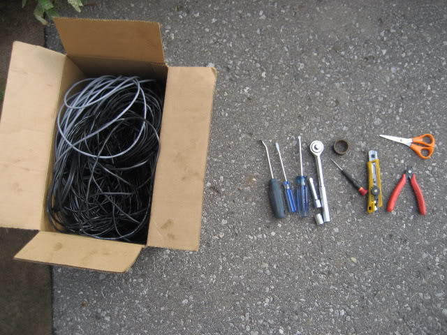
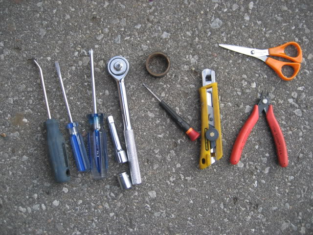
- Philips screwdriver
- Flathead screwdriver
- Door panel remover
- Tiny screw drive (cherry popper….you’ll know later on)
- Rachet with ½ mm socket
- Pliers **
- Wires (preferably 20 gauge….~18 is ok too)
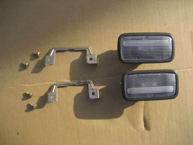
- 2x Door Courtesy Lights (2 brackets + 4 screws + pigtails) - these courtesy lights can be found on MOST hondas probably 2005 and older. NOTE: YOU NEED THE BRACKETS TO GO ALONG WITH IT!!! Most cars have the courtesy lights mounted onto a base molded on the panel. Very old Honda accords have brackets! Along with brackets, make sure you end up snipping 3” of wire with it. Most of them would come with a WHITE/BLUE wire and a GREEN/WHITE wire. Junkyard is your friend!
- Scissors
- Utility knife
- Layout Template (I will upload this once I’m done making it)
- Electric Tape
- Any utensil/tool to “fish” the wire. This includes anything that’s flexible like a metal hanger, 12 gauge wire, fishing tape, etc.
- PATIENCE & TIME!
- First aid kit **
- Small battery ** (to test the lights)
** Just incase
Let’s get to business:
Remove door panel (I’m starting off with the passenger side)
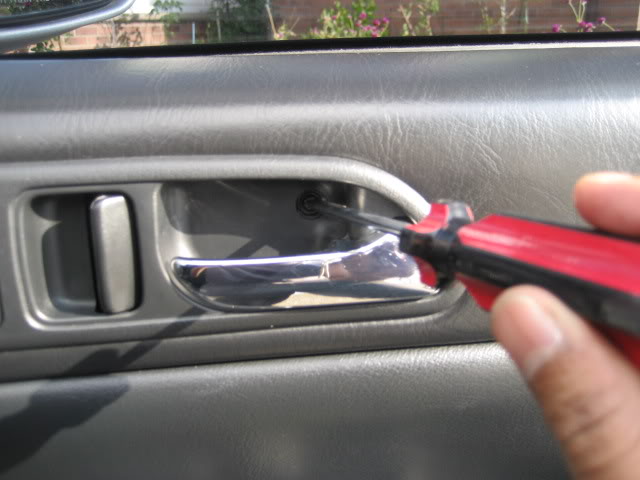
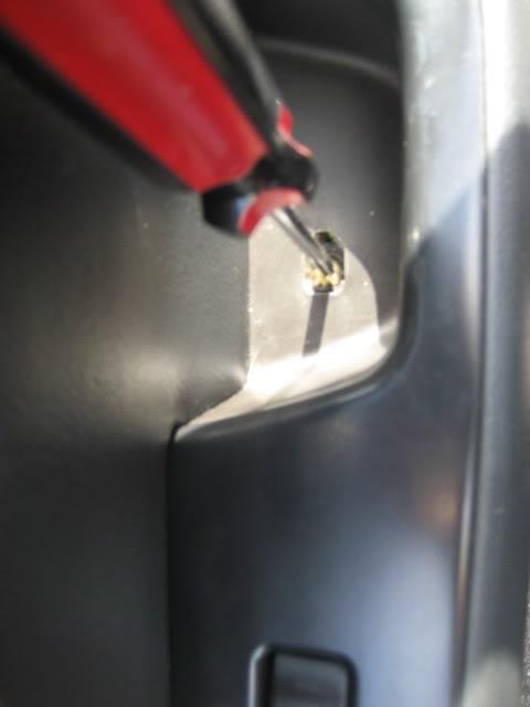
1. Remove the screw located behind the handle
2. Remove the screw in the door grip (the thing you grab to close the door)
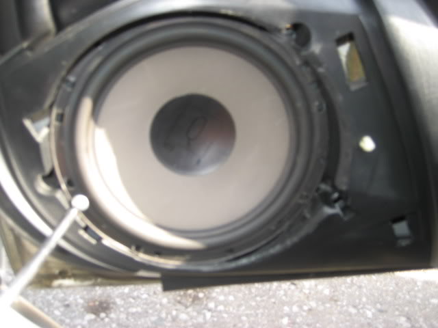
3. Remove speaker cover, remove screws holding it (I don’t have oem speakers, so yours may not look like mine) & remove the speakers
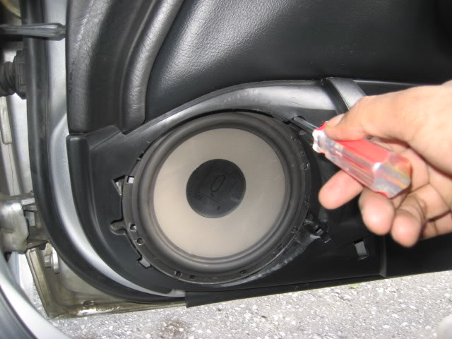
4. Remove the screws that hold the speaker enclosure
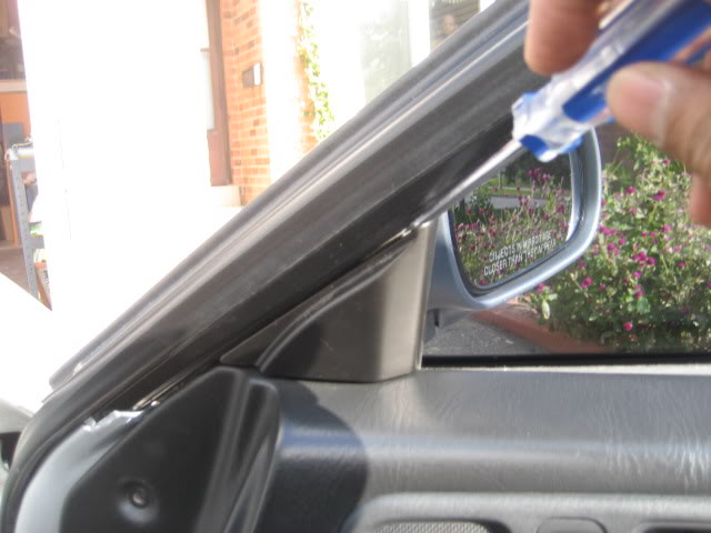
5. Remove the plastic push in tab near the side mirror
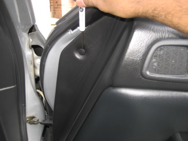
6. Remove the plastic cover beside the side mirror
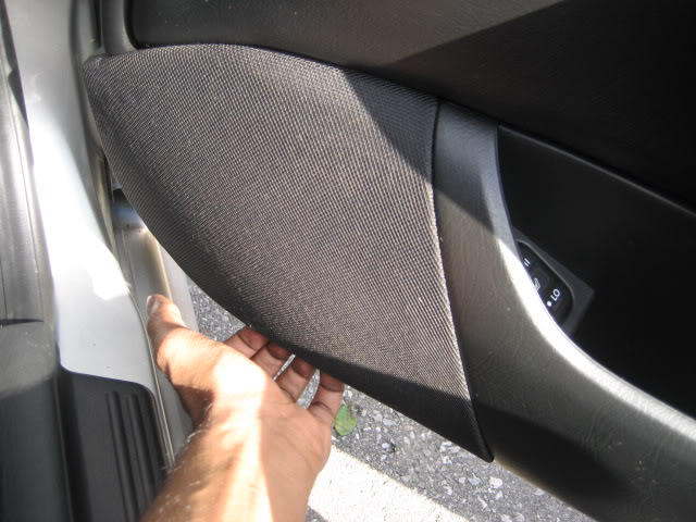
7. Using a panel remover and a cloth, gently tug on the panel until all clips have been popped out (start at the bottom and work your way up).
8. Turn the clip holding the metal rod from the door handle counter-clockwise and release the metal rod from the panel.
9. Unplug all wire harnesses
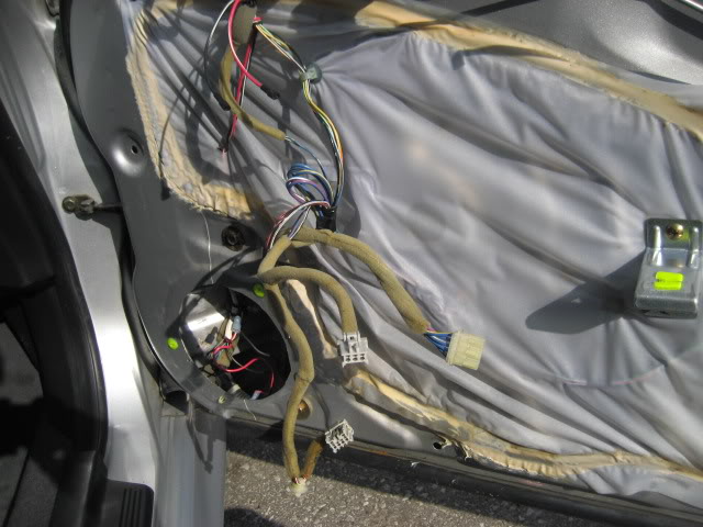
10. Once the door panel is out, place it upside down on a clean cardboard, cloth or any place where you can work on it comfortably and not get it scratched!
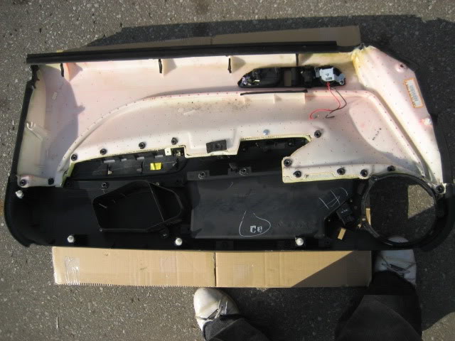
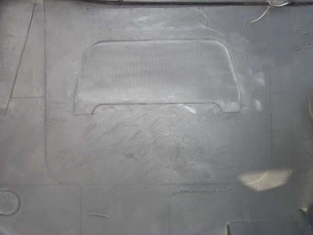
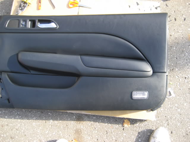
11. On the bottom (opposite of the speaker side), you will see an outline…which happens to be one for the door courtesy lights. Apparently, that “template” is pretty high up and also happens to be BIGGER than the courtesy light housing.
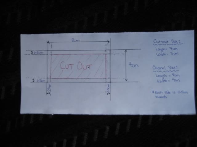
12. Download the template I have made (8cm x 4cm) and cut out the inner part (7cm x 3cm). From the edge of the housing to the place where you mount the brackets is 0.5cm inwards from all direction, hence the measurements.
Template Below: It's made to the exact measurement and the file itself is 8" x 11" (regular paper size). So all you have to do is print it, cut it & use it! (trying to make life quite simple for you guys)
https://www.canadianpreludeclub.com/ima ... mplate.jpg
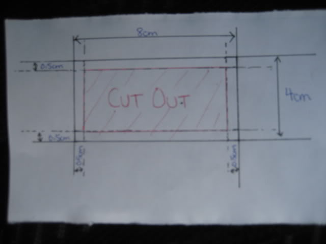
Just in case the measurements weren't right when you printed or something goes wrong, you can make one by yourself – it's simple
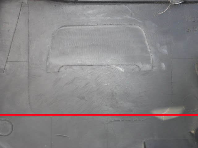
13. Using the bottom line shown below, tape my template so that the top of my bottom edge lines up with it. It’s confusing when you read it…so take a look at the pic below
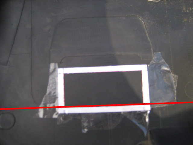
14. Once taped, you can either mark the outline with a pen/whiteout/pencil & remove the template or just leave it there and proceed to the next step
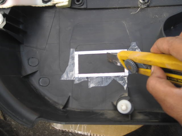
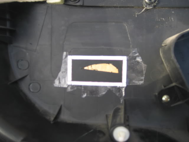
15. This is where you have to be patient. Since I didn’t have “professional/proper” tools, I opted for the utility knife. This takes time. Once you’ve cut out this piece, you might have to cut a few millimeters on each side. Note that this template is only providing you with a measurement that keeps you within the range of going over. Try fitting in the light housing in the hole and see where you have to trim some more.
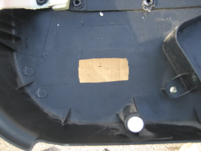
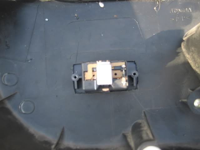
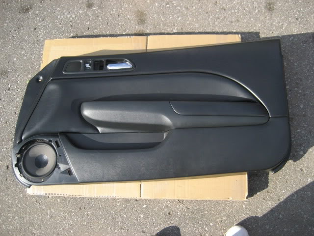
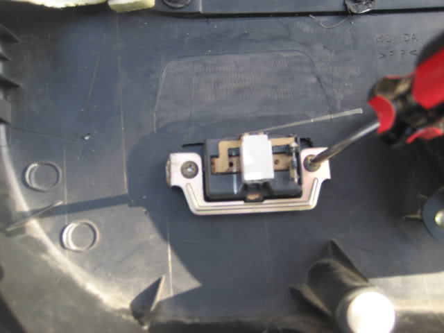
16. Once the housing fits perfectly, screw the brackets and there you have it – an “SH” door panel. Make sure the brackets are tightly screwed so you see no movement of the housing what’s so ever. Now let’s put this panel to a side.
Sadly, that was the easy part. Here comes the PITA part: How do you get the wires from the door into the body? This is where you have to be very patient and you need as MUCH light as you can get.
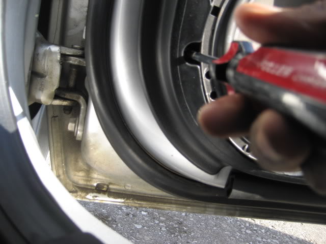
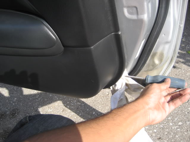
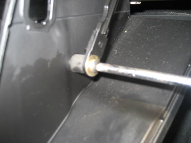
17. OPTION: Using a ratchet and a 12mm socket, remove the bolt holding the door hinge to the body, trust me this will help you access the plastic wire tubing/protector more easily (I was too lazy to remove the door)
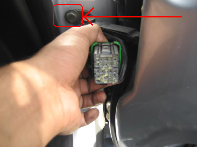
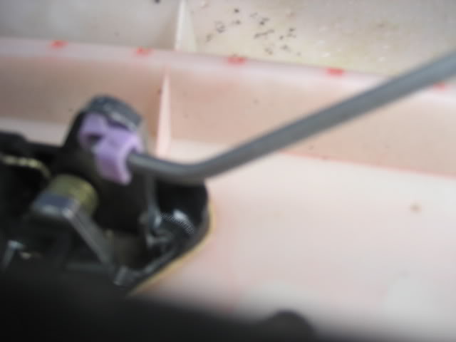
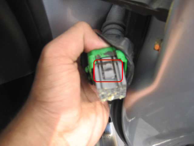
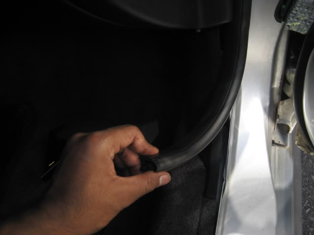
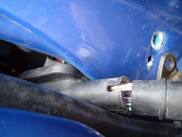
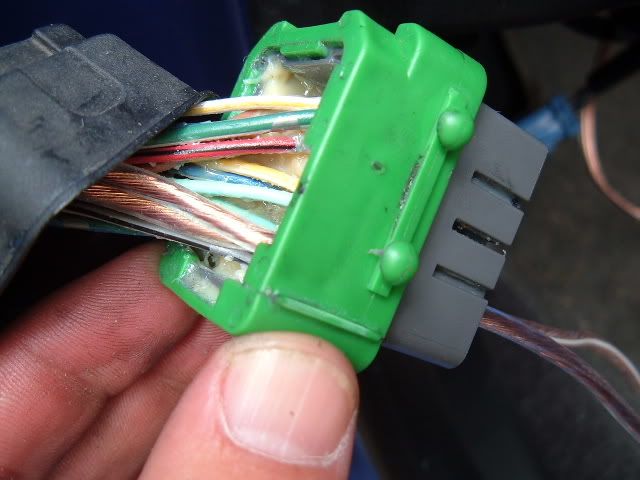
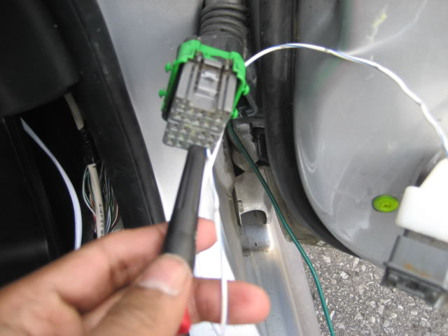
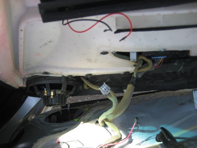
18. Remove the plastic cover (near the door) and you’ll have access to the green plastic thing that holds the block of wires. There is a release trigger on the top. Press it hard and toggle the block at the same time, pulling it outwards. It’s pretty stiff, but it’ll come out eventually. It should look something like this.
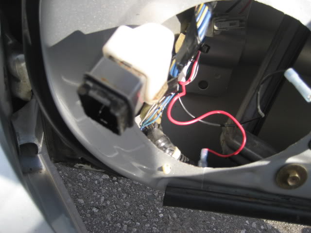
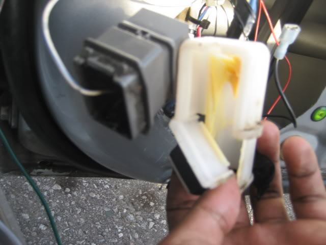
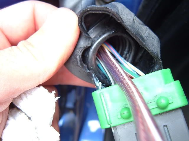
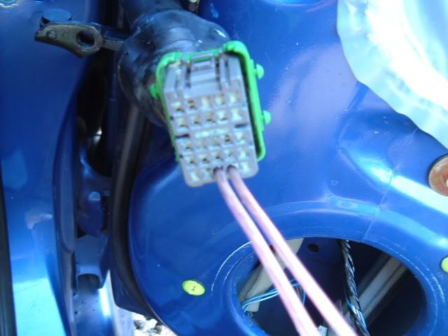
19. Remove the block from inside the door. This is kind of tricky to get to but it’s possible. Lift it up (apply some pressure) and it will come out. Bring it out through the speaker hole. This should look like this. Remove the plastic white stuff on the block (it’s taped) - just remove it and put it back on once you’re done.
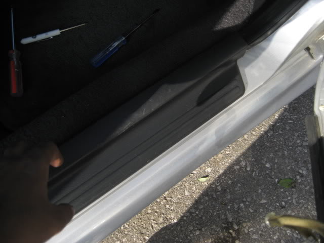
20. Now remove the door sill (just pops out) and passenger kick panel
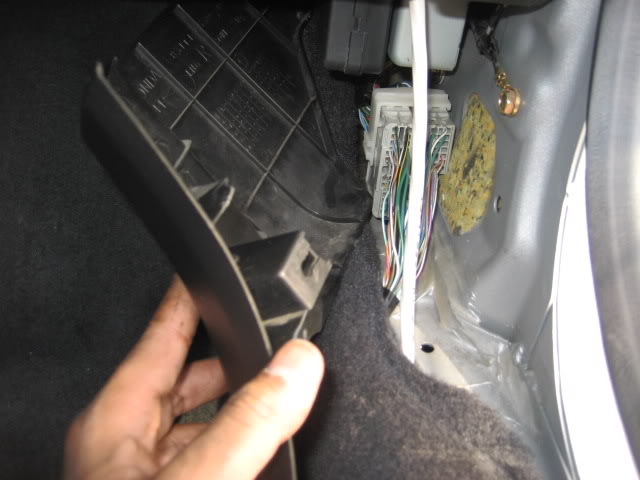
21. Unscrew the glove box and let it hang on the bottom. You DO NOT HAVE TO FULLY REMOVE IT. This will give you better access to the plastic tube
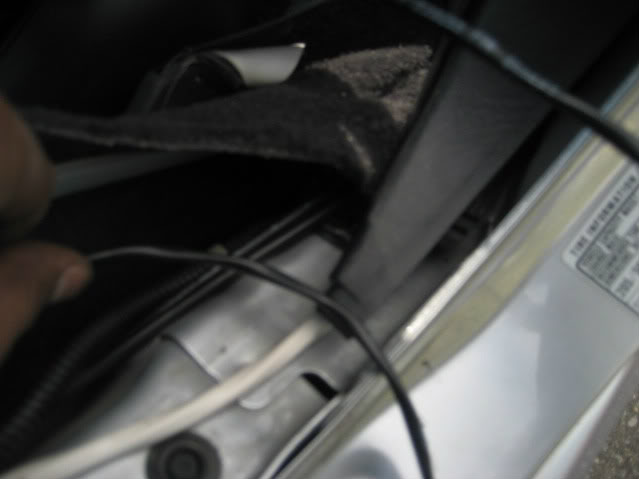
22. Using any fishing material mentioned above, gently insert it from the TUBE and not through the Passenger kick panel…trust me it’s a lot easier. This will kill most of your time….the fishing material should come inside into the passenger kick panel (sorry don’t have picture for this).
Sorry no pics for this...
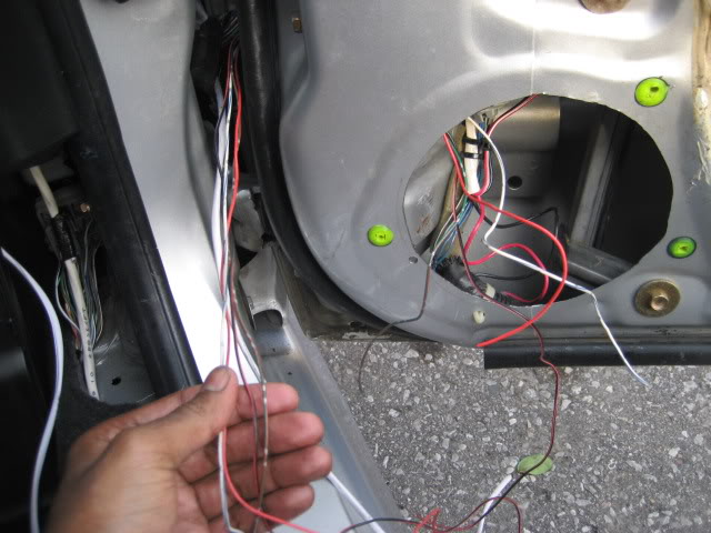
23. Here is the part where you must think about future mods involving anything related to wires being brought into the door from the body. For this mod, you need 2 WIRES (18-20 gauge). You can bring up to 6 wires (that I know of….hmm empty slots I mean…too lazy to count all).
24. Attach the two wires to the fishing material (from passenger footwell) and gently pull it outwards through the tube.
Following pictures are courtesy of JLude as I forgot to take pics (remind you….i had no one helping me and with all the cuts, scrapes and shit I was getting….along with this being a PITA, the camera was not on my mind):
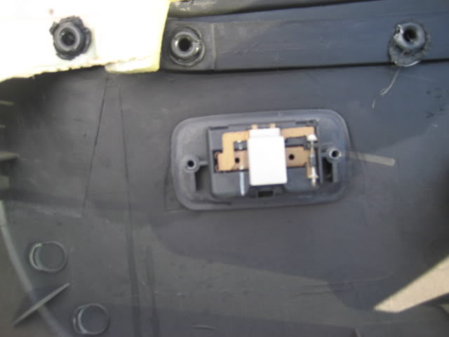
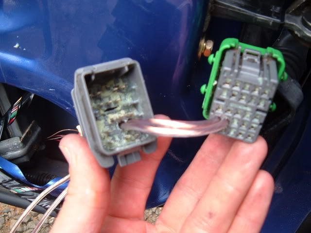
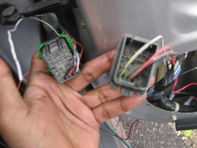
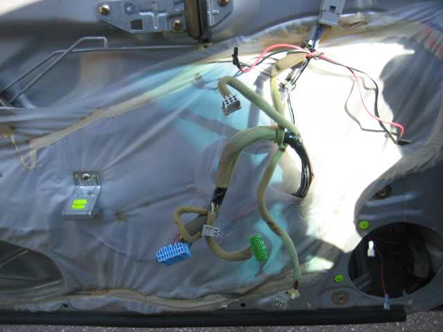
25. Take a close look at the block (that was on the outside of the door) and find the places that have empty slots.
Pics below (courtesy of JLude)
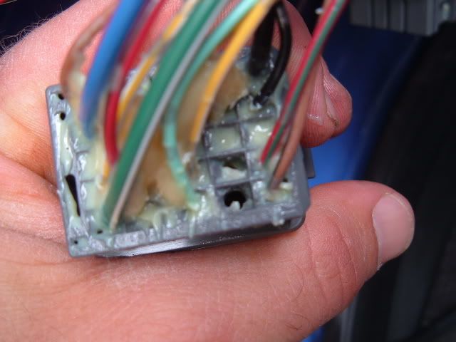
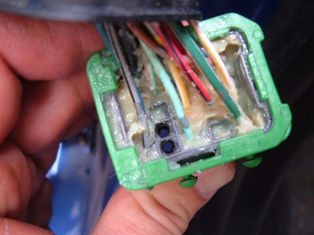
26. Using a tiny screw driver, poke the holes hard enough so that it breaks the tiny plastic barrier and comes through to the other side. This is why I called it the “cherry popper”. This hole is only good enough for a 20 gauge wire to go through. Anything more, you might have to use a small drill bit and drill through. For my lude the bottom 4 from the right were empty. So, go ahead and use that.
27. Now feed the wires through the outside block into the door and bring them through the speaker hole. Assuming you took the white plastic stuff off the inner block, feed the wire (remember: mirror image) through the inner block (inside of the door). After feeding all the wires through the inner block, place the white plastic cover back on!
28. Now for the inner block do the same BUT A MIRROR IMAGE OF IT. (Example: If you used the last 4 from the right on the bottom from the outside block….you must use the 4 from the left on the bottom of the inside block). Whatever you do, when you place them side by side, it MUST BE A MIRROR IMAGE!!!!! THIS STEP IS VERY IMPORTANTTT!!!
Pic below (courtesy of JLude)
29. Yes you see more than 2 wires (it’s because I’m doing another mod at the same time, will try and do a write up for that too)
30. This is where two people might be helpful but if you put ur mind to it, you can do it too. Don’t forget……it has to be like this
[ wire from passenger footwell -> plastic tube -> through the outer block -> through the door jam -> through the inner block -> into the door]
PULL the wires from the outside of both blocks simultaneously (to avoid tangles). Pull them one by one….Keep doing this for each wire and gently plug the blocks into their normal place. Now do you understand why they must be mirror image? It’s so that it can go through both of them and you can still pull on them on either side depending on how much you need on both sides.
31. [Inside the door] Connect those two wires to the “pigtails” that came with the housing. Remember which one you connected to. White/blue (positive)….Green/blue (negative).
Note: When you get lights from a junkyard....no matter what car they come off from (assuming either Honda or Acura)....one wire will be white/blue and the other will be green/some other colour.
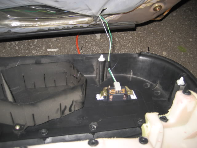
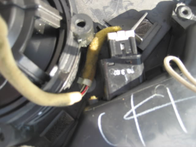
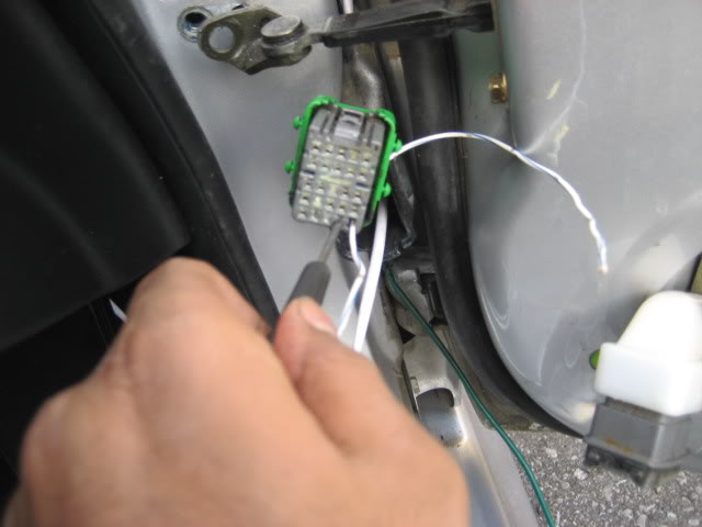
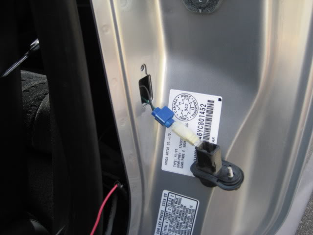
32. [Inside the passenger footwell] In the kick panel, you will see a 14 PIN connector. Locate a WHITE/BLUE wire and using T-taps, splice the positive wire into that [White/Blue -> White/Blue].
Locate another wire (GREEN/ORANGE) and tap the negative wire to that. [Green/Something -> Green Orange] Make sure they are very well spliced/connected.
If you did not have pigtails....whichever one is positive connect that to (WHT/BLU)....and which ever one is negative connect that to (GRN/ORN)
**** You can run the ground wire all the way to the door trigger….but this is much faster****
Following pics: (courtesy of Shimee)
As you can see the GREEN/ORANGE wire is the 2nd wire below the WHITE/BLUE. These two wires are what you want!


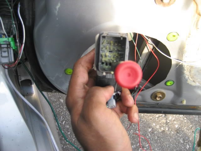
33. Once connected, take the other housing (not the one mounted to the panel) and connect it to the other end (on the door) and see if lights up. If it does…MOVE ON…..if it doesn’t…uh oh....go back and see where you went wrong....
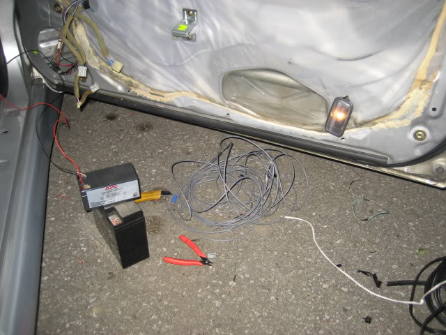
Yes I have it hooked to a battery…but it should be the same thing….
34. *****IF YOU REMOVED THE DOOR HINGE BOLT, this is where you should bolt it back in!!!!*****
35. Put back the door panel (In reverse order)
36. Put back the door sills, door kick panel – all are in reverse over.
37. Do the same for the Driver side. Note: There are more harnesses on this side…so be careful when pulling out the door panel.
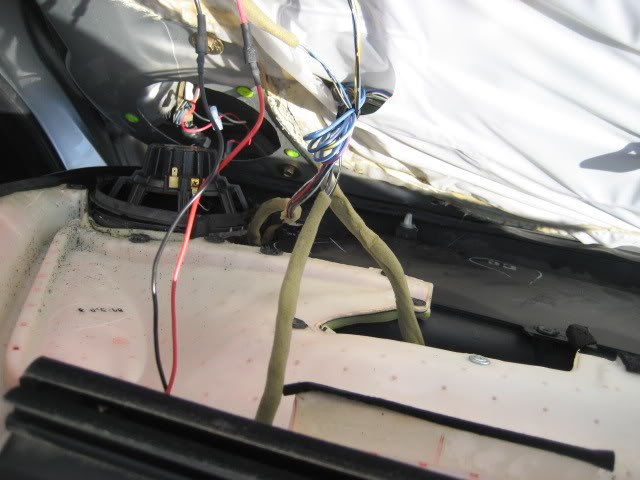
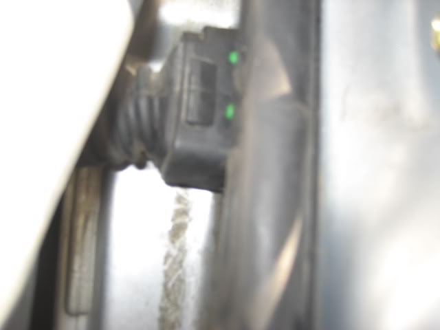
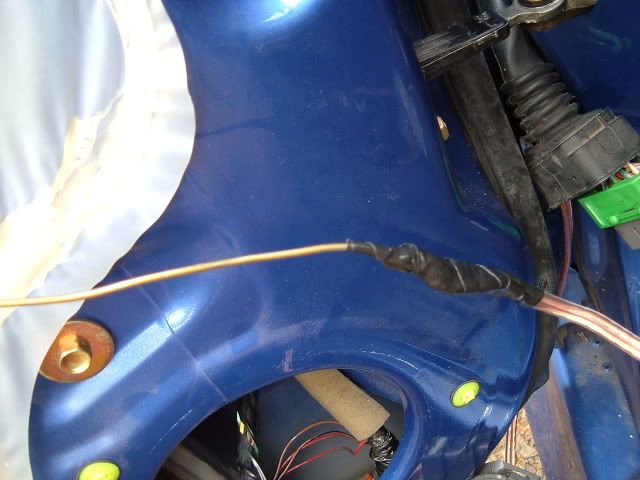
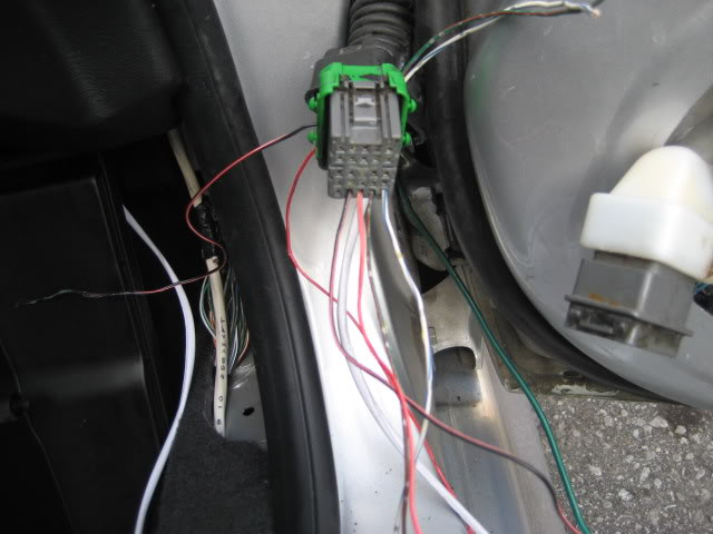
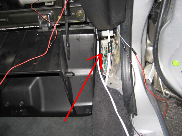
38. When getting power for the driver side, run the wire all the way to the driver side B-pillar. Not as easy as the passenger side, I know. At the bottom of the b-pillar you will see a series of wires including a WHITE/BLUE (positive) and GREEN (negative).
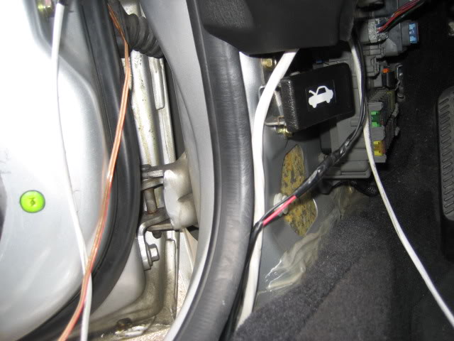
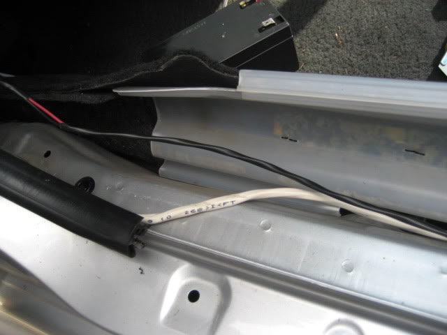
I wasn’t able to capture the WHITE/BLUE wire as it was deep inside and gave me a hard time trying to get a photo…but you can see where the red one goes from the pic above….it’s there trust me…
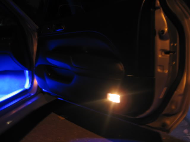
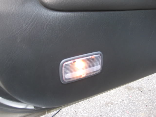
39. There you go! Now you have courtesy lights!!!
Alright listen up, READ EVERYTHING before actually starting this mod. There are important things to consider and sometimes there might be quite useful things you’d find in reading this prior to actually doing it. In saying that…
DISCLAIMER: Canadian Prelude Club and I (infamouz) are not responsible/accountable for any errors, damage, unwanted results that you may come across or experience! DO THIS AT YOUR OWN RISK!
Let’s move on…if you do not understand what’s going on at a certain step, feel free to comment on this post or PM me. I’ll try to explain it as best I can…
What you need:
- Philips screwdriver
- Flathead screwdriver
- Door panel remover
- Tiny screw drive (cherry popper….you’ll know later on)
- Rachet with ½ mm socket
- Pliers **
- Wires (preferably 20 gauge….~18 is ok too)
- 2x Door Courtesy Lights (2 brackets + 4 screws + pigtails) - these courtesy lights can be found on MOST hondas probably 2005 and older. NOTE: YOU NEED THE BRACKETS TO GO ALONG WITH IT!!! Most cars have the courtesy lights mounted onto a base molded on the panel. Very old Honda accords have brackets! Along with brackets, make sure you end up snipping 3” of wire with it. Most of them would come with a WHITE/BLUE wire and a GREEN/WHITE wire. Junkyard is your friend!
- Scissors
- Utility knife
- Layout Template (I will upload this once I’m done making it)
- Electric Tape
- Any utensil/tool to “fish” the wire. This includes anything that’s flexible like a metal hanger, 12 gauge wire, fishing tape, etc.
- PATIENCE & TIME!
- First aid kit **
- Small battery ** (to test the lights)
** Just incase
Let’s get to business:
Remove door panel (I’m starting off with the passenger side)
1. Remove the screw located behind the handle
2. Remove the screw in the door grip (the thing you grab to close the door)
3. Remove speaker cover, remove screws holding it (I don’t have oem speakers, so yours may not look like mine) & remove the speakers
4. Remove the screws that hold the speaker enclosure
5. Remove the plastic push in tab near the side mirror
6. Remove the plastic cover beside the side mirror
7. Using a panel remover and a cloth, gently tug on the panel until all clips have been popped out (start at the bottom and work your way up).
8. Turn the clip holding the metal rod from the door handle counter-clockwise and release the metal rod from the panel.
9. Unplug all wire harnesses
10. Once the door panel is out, place it upside down on a clean cardboard, cloth or any place where you can work on it comfortably and not get it scratched!
11. On the bottom (opposite of the speaker side), you will see an outline…which happens to be one for the door courtesy lights. Apparently, that “template” is pretty high up and also happens to be BIGGER than the courtesy light housing.
12. Download the template I have made (8cm x 4cm) and cut out the inner part (7cm x 3cm). From the edge of the housing to the place where you mount the brackets is 0.5cm inwards from all direction, hence the measurements.
Template Below: It's made to the exact measurement and the file itself is 8" x 11" (regular paper size). So all you have to do is print it, cut it & use it!
https://www.canadianpreludeclub.com/ima ... mplate.jpg
Just in case the measurements weren't right when you printed or something goes wrong, you can make one by yourself – it's simple
13. Using the bottom line shown below, tape my template so that the top of my bottom edge lines up with it. It’s confusing when you read it…so take a look at the pic below
14. Once taped, you can either mark the outline with a pen/whiteout/pencil & remove the template or just leave it there and proceed to the next step
15. This is where you have to be patient. Since I didn’t have “professional/proper” tools, I opted for the utility knife. This takes time. Once you’ve cut out this piece, you might have to cut a few millimeters on each side. Note that this template is only providing you with a measurement that keeps you within the range of going over. Try fitting in the light housing in the hole and see where you have to trim some more.
16. Once the housing fits perfectly, screw the brackets and there you have it – an “SH” door panel. Make sure the brackets are tightly screwed so you see no movement of the housing what’s so ever. Now let’s put this panel to a side.
Sadly, that was the easy part. Here comes the PITA part: How do you get the wires from the door into the body? This is where you have to be very patient and you need as MUCH light as you can get.
17. OPTION: Using a ratchet and a 12mm socket, remove the bolt holding the door hinge to the body, trust me this will help you access the plastic wire tubing/protector more easily (I was too lazy to remove the door)
18. Remove the plastic cover (near the door) and you’ll have access to the green plastic thing that holds the block of wires. There is a release trigger on the top. Press it hard and toggle the block at the same time, pulling it outwards. It’s pretty stiff, but it’ll come out eventually. It should look something like this.
19. Remove the block from inside the door. This is kind of tricky to get to but it’s possible. Lift it up (apply some pressure) and it will come out. Bring it out through the speaker hole. This should look like this. Remove the plastic white stuff on the block (it’s taped) - just remove it and put it back on once you’re done.
20. Now remove the door sill (just pops out) and passenger kick panel
21. Unscrew the glove box and let it hang on the bottom. You DO NOT HAVE TO FULLY REMOVE IT. This will give you better access to the plastic tube
22. Using any fishing material mentioned above, gently insert it from the TUBE and not through the Passenger kick panel…trust me it’s a lot easier. This will kill most of your time….the fishing material should come inside into the passenger kick panel (sorry don’t have picture for this).
Sorry no pics for this...
23. Here is the part where you must think about future mods involving anything related to wires being brought into the door from the body. For this mod, you need 2 WIRES (18-20 gauge). You can bring up to 6 wires (that I know of….hmm empty slots I mean…too lazy to count all).
24. Attach the two wires to the fishing material (from passenger footwell) and gently pull it outwards through the tube.
Following pictures are courtesy of JLude as I forgot to take pics (remind you….i had no one helping me and with all the cuts, scrapes and shit I was getting….along with this being a PITA, the camera was not on my mind):
25. Take a close look at the block (that was on the outside of the door) and find the places that have empty slots.
Pics below (courtesy of JLude)
26. Using a tiny screw driver, poke the holes hard enough so that it breaks the tiny plastic barrier and comes through to the other side. This is why I called it the “cherry popper”. This hole is only good enough for a 20 gauge wire to go through. Anything more, you might have to use a small drill bit and drill through. For my lude the bottom 4 from the right were empty. So, go ahead and use that.
27. Now feed the wires through the outside block into the door and bring them through the speaker hole. Assuming you took the white plastic stuff off the inner block, feed the wire (remember: mirror image) through the inner block (inside of the door). After feeding all the wires through the inner block, place the white plastic cover back on!
28. Now for the inner block do the same BUT A MIRROR IMAGE OF IT. (Example: If you used the last 4 from the right on the bottom from the outside block….you must use the 4 from the left on the bottom of the inside block). Whatever you do, when you place them side by side, it MUST BE A MIRROR IMAGE!!!!! THIS STEP IS VERY IMPORTANTTT!!!
Pic below (courtesy of JLude)
29. Yes you see more than 2 wires (it’s because I’m doing another mod at the same time, will try and do a write up for that too)
30. This is where two people might be helpful but if you put ur mind to it, you can do it too. Don’t forget……it has to be like this
[ wire from passenger footwell -> plastic tube -> through the outer block -> through the door jam -> through the inner block -> into the door]
PULL the wires from the outside of both blocks simultaneously (to avoid tangles). Pull them one by one….Keep doing this for each wire and gently plug the blocks into their normal place. Now do you understand why they must be mirror image? It’s so that it can go through both of them and you can still pull on them on either side depending on how much you need on both sides.
31. [Inside the door] Connect those two wires to the “pigtails” that came with the housing. Remember which one you connected to. White/blue (positive)….Green/blue (negative).
Note: When you get lights from a junkyard....no matter what car they come off from (assuming either Honda or Acura)....one wire will be white/blue and the other will be green/some other colour.
32. [Inside the passenger footwell] In the kick panel, you will see a 14 PIN connector. Locate a WHITE/BLUE wire and using T-taps, splice the positive wire into that [White/Blue -> White/Blue].
Locate another wire (GREEN/ORANGE) and tap the negative wire to that. [Green/Something -> Green Orange] Make sure they are very well spliced/connected.
If you did not have pigtails....whichever one is positive connect that to (WHT/BLU)....and which ever one is negative connect that to (GRN/ORN)
**** You can run the ground wire all the way to the door trigger….but this is much faster****
Following pics: (courtesy of Shimee)
As you can see the GREEN/ORANGE wire is the 2nd wire below the WHITE/BLUE. These two wires are what you want!
33. Once connected, take the other housing (not the one mounted to the panel) and connect it to the other end (on the door) and see if lights up. If it does…MOVE ON…..if it doesn’t…uh oh....go back and see where you went wrong....
Yes I have it hooked to a battery…but it should be the same thing….
34. *****IF YOU REMOVED THE DOOR HINGE BOLT, this is where you should bolt it back in!!!!*****
35. Put back the door panel (In reverse order)
36. Put back the door sills, door kick panel – all are in reverse over.
37. Do the same for the Driver side. Note: There are more harnesses on this side…so be careful when pulling out the door panel.
38. When getting power for the driver side, run the wire all the way to the driver side B-pillar. Not as easy as the passenger side, I know. At the bottom of the b-pillar you will see a series of wires including a WHITE/BLUE (positive) and GREEN (negative).
I wasn’t able to capture the WHITE/BLUE wire as it was deep inside and gave me a hard time trying to get a photo…but you can see where the red one goes from the pic above….it’s there trust me…
39. There you go! Now you have courtesy lights!!!

.
In a world full of copies, be an original.
.
Graphic Design: Indezyne | Rare Prelude Parts: InfamouzJDM